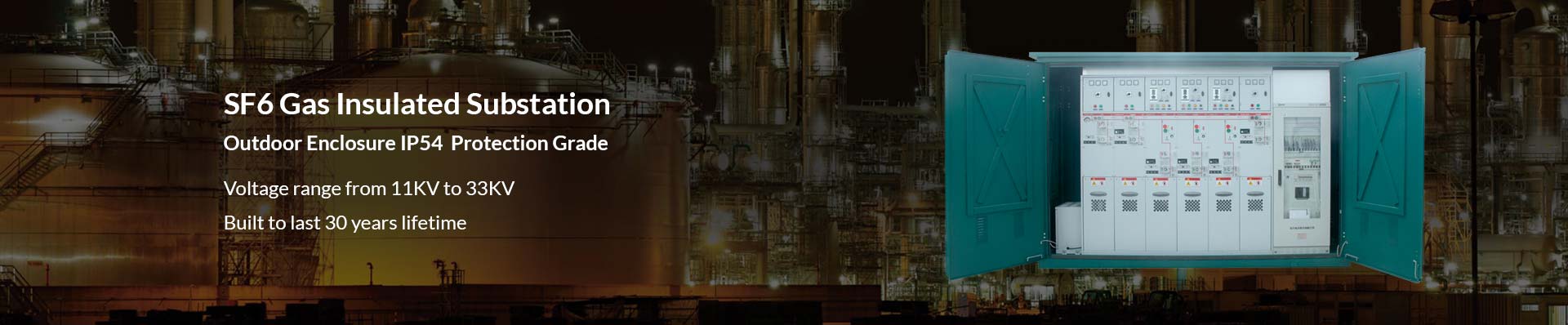
SF6 Gas Insulated Substation
The SF6 gas insulated substation (GIS) is assembled by several SF6 gas insulated switchgear configurations in an outdoor enclosure which could reach IP54 protection grade. With the advantage of SF6 gas insulating ability (the interrupting arcs capability is 100 times more than air), gas insulated substation could operate in stable condition for more than 30 years. All of the live components was in the completely sealed stainless steel tank filling with SF6 gas, this design could ensure the GIS more reliable and few maintenances during the lifetime.
Medium voltage gas insulated substation normally assembled by 11KV or 33KV gas insulated switchgear, these two types gas insulated substations could satisfy mostly application requirements for the projects.
GIS gas insulated switchgear substation is normally designed in economic and compact layout for construction, so the advantages of the GIS substation listed as following:
It takes only 1/10th space compared to normal size switchgear substation. So the GIS gas insulated substation is the best choice for the projects which is small space of compact design.
2. Because of the SF6 gas in the sealed tank, so the gas insulated substation components work in stable condition, it will be much less fault than the air-insulated substation.
3.Free maintenance due to the reliable performance.
The disadvantage of GIS gas insulated substation:
1. The cost will be higher than the normal substations
2. When there is a fault, it will take much more time to find the causing reason and repair the GIS substation.
3. Each module cabinet must equip with one SF6 gas pressure gauge to monitor the gas pressure inside, the gas pressure reduction of any module will cause the fault of the whole gas insulated substation.
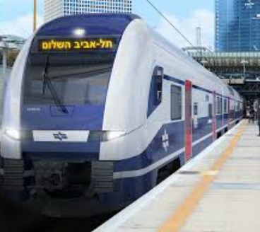
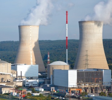
Applications of SF6 Gas Insulated Substation


Gas Insulated Substation:The Complete Guide for Importers
Electrical power demand increases every day.
That results to a lot of power corporation across the globe who are availing the power whenever and wherever it’s required.
Presenting power has become a significant challenge to the power corporations.
The power corporations handle the generation, transmission and the distribution of power via different power plants.
Substations that has switchgear is widely utilized for this purpose.
You see, switchgear systems in distribution and transmission are utilized to control the power flow.
It’s also utilized to guarantee that the system malfunctions and failures remain limited to a particular area and particular technical limit.
It will ensure the overall network stability.
In this e-Book, we will provide you with everything you need to know about gas insulated switchgear substation.
This may cover the following just to name a few:
- what does gas insulated substation mean?
- features of gas insulated substation
- advantages of gas insulated substation
- gas insulated substation types
- components of a gas insulated substation
Without further ado, let’s get into the business.
Chapter 1: Gas Insulated Substation Definition: What is a GIS Substation?
A gas insulated substation (GIS) is considered a high voltage switchgear.
The main structures are covered in a tight setting along with sulfur hexafluoride gas as the insulating medium.
In case you didn’t know yet, GIS substation originated from Japan.
It’s the place where there was a massive need to build technology to make gas insulated substations as compact as possible.
The clearance needed for the phase to phase to the ground for every equipment is much less than that is necessary for an air insulated substation.
You see:
The overall space needed for a GIS is ten percent of that required for an average substation.
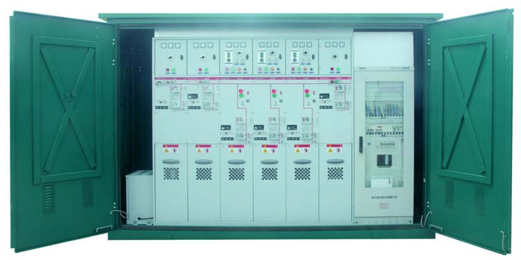
SF6 GIS Gas Insulated Substation
GIS gas insulated substation provide other advantages apart from the lowered space requirements.
As mentioned earlier, the 11kv substation is enclosed within a building.
Therefore, a GIS is less delicate to pollution, such as salt, sand, or big amount of snow.
The initial cost of constructing an sf6 substation is higher than construction an air insulated.
The good thing is that the maintenance and operation expenses of GIS are less.
Sounds amazing, isn’t it?
The primary applications for GIS substations are the following:
Environmentally Sensitive Installations
Gas insulated substation technology is sought-after and widely utilized in arctic and desert regions.
That’s mainly because it can be enclosed in an establishment along with environmental control.
You see:
GIS is also composed of electrical components in a Faraday cage and is thus completely protected from lighting.
Urban Installations
Gas insulated substation technology can be utilized for installations in regions where the price of aesthetic or real estate appeal is a crucial consideration.
When it comes to indoor installations, creating an air insulated substations inside usually is not practical.
However, a GIS substation layout could go inside building easily and conveniently.
High Voltage Installations
The higher the voltage, the more promising GIS becomes.
As you might be aware, the footprint of a 765kv average substation is substantial.
The gas substation technology enables a massive size reduction.
What Does Gas Insulated Substation Mean?
An electrical or switchgear is a generic term that covers all the switching devices connected with the main power.
It also covers every device connected with:
- control
- metering and;
- regulating the power system
Assembly of such devices logically creates a switchgear.
That’s the basic definition of a gas insulated substation.
You see:
GIS high voltage is a compact metal encapsulated switchgear which includes high voltage components.
This covers disconnectors and circuit breakers that can be operated safely in confined areas.
GIS is utilized where space is minimal.
An example of this extension, hydro power plants, industrial plants, on offshore platforms, on roofs, and within city buildings.
What are the Features of Gas Insulated Substation?
After understanding the meaning of gas insulated substation, it’s time to understand its amazing features.
Reliability
Reliable electric supply is very crucial in urban networks.
That’s because it is where load densities are high, and users are prone to interruptions.
The dependability of sf6 substation is crucial for the:
- continuous operation of consumer utilities
- the response in emergency management
- recovery
- for mitigation awareness
Compared to Air Insulated Substation, GIS unit is much dependable.
That’s because it’s less susceptible to faults.
Plus, it has less to zero maintenance requirement as well.
Did you know that it doesn’t need any maintenance requirement for at least 40 years?
Creepage Distance
You are aware that creepage is considered as the smallest distance between 2 conductive elements.
This is measured with the surface of the insulation.
The electric discharge on the ground of insulation material gives corrosion on that region of the surface.
Enough and appropriate creepage distance safeguards that localized corroded conduction path.
That process is termed as tracking.
The level of tracking needed varies upon 2 significant considerations:
- the degree of pollution within the atmosphere
- the comparative tracking index
Tracking these destroys the insulating material on a regular basis happens as a result of one of the reasons:
- altitude at which equipment is to be operated
- chemicals that result in corrosion
- pollutants present within the air
- moisture or humidness in the climate
As per the mentioned reasons above, a GIs substation design doesn’t require to maintain any creepage distance.
That’s mainly because it’s a compact switchgear free from the environment.
- Clearance Distance
On the other hand, clearance distance refers to the smallest distance between 2 conductive elements that is measured via air.
It helps to avoid the dielectric breakdown that happens between 2 electrodes because of the ionization of air.
What’s more:
The dielectric among the electrodes is influenced by the relative humidity, temperature as well as the level of pollution within the setting.
Gas insulated substation, on the other hand, is compact made which is independent of the environment.
Manufacturing
When we talk about manufacturing, an AIS is no doubt a conventional substation.
It needs a big space for installation.
Meanwhile, an 11kv substation is compact and needs less space for installation.
Space needed for GIS substation layout is less than 20 percent of AIS.
Maintenance
The rate of malfunction of disconnecting circuit breaker and switch in GIS is ¼ of that of air-insulated substation, and 1/10 when it comes to the busbar.
Therefore, the maintenance expense of a gas-insulated becomes less than that of air insulated for a lifetime.
The good thing here is that GIS needs less maintenance need.
That’s because of its effective protection and design from an external element.
However, when we talk about emergency maintenance, a highly-skilled personnel is needed.
Furthermore, the operating life of substation design is over 50 years, and no major inspection is needed before the initial 25 years.
Advantages of Gas Insulated Substations
This is probably the apparent fact that GIS assumes striking part for productive and solid force dissemination.
It has different preferences over regular air-insulated substations.
A percentage of the prevalent focal points of gas insulated substations are presented as takes after:
- A gas insulated substation is very safe to environmental contaminations as well as conditions.
The blackout gets lessened and combined along with their prolonged solid quality, and the general upkeep costs are reduced.
- Such substations are by, and big found closer to the heap focuses.
Thus, it lowers the misfortunes in conveyance and transmission systems.
- The GIS can be employed effectively as a part of waterfront zones salt contamination, urban and mechanical areas where contamination and space are the major concerns.
- The GIS Can be presented either inside or underground and in those vigorously populated regions.
- The gas insulated substation owned just approximately ten percent of the space needed by a routine air protected substation.
- It can be assembled right at the shop, and the modules can be custom-built in the plant immediately.
- The majority are very reliable, compared to air insulated substations.
- It occupies less space compared to a standard substation.
Therefore, GIS is the most favorited where space for substation is a bit small.
Gas Insulated Substation Types
There are different types of gas insulated substation.
They are the following:
- Metal Enclosed Substation
This type of substation has an earthed metallic enclosure.
It is composed of three major compartments:
- the rear or the back compartment for cable connection and current transformer
- the front compartment is for the circuit breaker
- the top compartment is for the bus bar assembly
Typically, metal enclosed substations feature compartments along with metal partitions.
These partitions are supposed to be earthed.
Thus, this is also referred to as metal clad switchgear.
Some of this might have one or more non-metallic partitions.
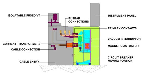
Metal Enclosed Indoor Substation
Did you know that there are 2 major types of metal enclosed indoor substation?
- horizontal draw out and horizontal isolation
- horizontal draw out and vertical isolation
Normally, indoor substation housing has 3 chambers, namely:
- current transformer cub cable connection chamber (rear)
- busbar chamber (top)
- circuit breaker chamber (front)
Metal Enclosed Outdoor Substation
This type of substation is similar to the second type, apart from its external housing.
You see:
The external housing or the metal enclosure is made from a welded sheet steel along with rain shield and slanting roof.
The housing is made in such a manner, which it becomes ideally appropriate for the outdoor application.
This kind of 33kv substation design isn’t typically utilized except for special utilities.
An example of this is city distribution networks along with underground cable system.
Components of Gas Insulated Substation
The gas insulated substations have the following components:
- BUS : Bus-bar
- CHd : Cable Sealing End
- VT : Voltage Transformer
- CT : Current Transformer
- HSES : High-Speed Earthing Switch
- ES : Earthing Switch
- DS : Disconnecting Switch
- CB : Circuit Breaker
Circuit Breaker
Under the short circuit cases, the current might reach tens of thousands of amperes.
Its responsibility is to block such currents as fast as possible to prevent the damage to the equipment.
Gas Insulated Substation Components
One of the functions of the main circuit breaker is to de-energy faulted:
- buses
- transformer banks
- transmission lines
You see:
An opening operation is initiated by protective relays.
These relays are typically installed remotely in a control room and relay.
That operation might also involve reclosing of the circuit breaker automatically many times.
The closing or opening of the circuit breaker can also be initiated through human intervention from various locations.
This might include from the:
- circuit breaker mechanism
- from the relay
- control panels from the circuit breaker
- electrically from the LCC
- from supervisory controls remote from the GIS
- control panels remote from the circuit breaker
Generally, a circuit breaker isn’t blocked from closing and/or closing by the status of either an earthing switch or disconnect switch.
However, a circuit breaker is blocked from operating by parameters which affect its excellent function.
This covers:
- pole disagreement tripping
- low mechanism pressure
- low interrupting and insulating gas density
- monitoring of the right circuit breaker status before initiating an operation.
For example, a circuit breaker needs to be in a closed position completely before an open operation can be initiated.
Equally, a circuit breaker needs to be in the open position completely before a close operation could be initiated.
On the other hand, the signal of the circuit breaker status could be tracked at the circuit breaker mechanism cabinet.
That can be accomplished through mechanically operated semaphores, at the relay, at the LCC, and control panels remote from the circuit breaker.
Disconnector
In case you didn’t know yet, a disconnector or isolator is employed for electrical isolation of the circuit parts.
It disconnector switches could be a single pole. The group operated or three poles operated.
They are very slow acting and working at offload.
Disconnectors should be designed and tested carefully to break small charging current without producing too much high overvoltage.
Voltage Transformer
The following must be considered and specific in the selection of a voltage transformer.
- Accuracy class
- Thermal rating of the primary winding
- The ratio of primary voltage to every secondary winding voltage
- Number of taps in every secondary winding
- Number of secondary windings
Local Control Cubicle
Also referred to as LCC, this is the interface cubicles to every secondary system of a substation that represent a protection and station control.
It includes alarm and control functions as well as the proper distribution of the auxiliary power supply
Generally, every cabinet must include the following for protection, indication, and control of switches, associated components, and circuit breakers:
- Control switches for dc and ac supply to every compartment
- 1 or 2 red light-emitting diodes and 1 green for every circuit breaker
- 1 open-close control switch for every motor-operated grounding switch
- 1 remote-local switch for every 3-phase circuit breaker
- 1 control switch for every 2-phase circuit breaker
Current Transformer
A current transformer is situated inside for three phase gas compartment and outside the enclosure.
Its purpose is to lessen access to moisture and to destroy gas-tight bushing for the secondary connections.
The current rating of Current Transformer is at least 120 percent of rated primary current.
A current transformer is generally installed within the circuit breaker bushing turrets.
However, particular designs like transformer connections and direct cable might need standalone current transformers.
To access the main bus, earth switches should best isolated as well as the voltages injected via the earthing switch into the bus.
Such tests are performed along with the main bus denergized and remoted from any operational areas of the remaining gas insulated substation installation.
Cable Connection
The following ought to be considered and specific in the design of the cable connection.
The values must be selected from IEEE Standard 48-1990.
- Power frequency factory withstand voltage – kV rms phase to ground
- Peaks short circuit current – kA peak
- Short-time current – kA rms for 1 s or 3 s
- Continuous current – A rms
- Basic insulation level – kV peak
- Voltage – kV rms phase to phase
- Maximum dielectric fluid pressure for cable systems – kPa
Gas Chambers and Zones
A gas chamber is referred as an enclosure which includes gas isolated from the other chambers and the atmosphere.
Two or more gas chambers might be connected externally with tiny diameter gas pipes.
This is defined as a portion of the gas insulated substation installation which includes one or more gas chambers.
This gas chambers offers a common gas monitoring system and which gas density increases in unison.
Voltage Transformers
Comparable to the air insulated substation, 33kv substation has voltage transformers.
Its role is to lessen the bus high voltage to reduce control levels of 120/208 voltages for:
- metering
- control
- relays and;
- similar functions
Additional tests, insulation integrity, and common turn ration should be done.
Earthing Switches/Three-Position Disconnect
At voltages in the series of 34.5 kV to 3-phase Gas Insulated Substation, a 3-position switch is typically installed.
That switch combines a disconnect switch together with an earthing switch.
Along with one blade and operator, the switch could be situated into the:
- earthed position
- open position
- closed position
Generally, 3-position switches have similar operation mechanisms method and type of locating switch states as disconnect switches.
When 3-way switches are set up, and gis in substation will be operated distantly, provisions should be done.
It will replace the position of selector switch to prevent a necessity for a person to travel to the substation and change the switch manually.
High-Speed Earthing Switches
Did you know that high speed earthing switches are unique to gas insulated substation layout?
That’s because they aren’t typically utilized in AIS.
Their primary function is similar to the earthing switches in AIS as well as non-fault earthing switches in gas insulated substation installation.
They also cover the similar function as portable personnel earth connections that are created with hook sticks.
You see, this high-speed earthing switches feature an added capability of closing the energized conductor.
It creates a short circuit without suffering from any significant damage to the enclosure or switch.
They are employed to earth various active substation elements like:
- main buses
- transformer banks and;
- transmission lines
In various GIS installations, these switches are utilized to initiate protective relay functions.
Often, they aren’t employed to earth voltage transformers or circuit breakers.
High-speed earthing switches are also created and made to breakdown electrostatically inductive currents and induced capacitive currents.
Non-Fault Initiating Earthing Switches
This is utilized in GIS installation for similar staff protection use as those in an AIS.
They are the same to a portable personnel earthing connection that is constructed with hook stick.
They are employed to earth various de-energized substation elements like:
- voltage transformers and;
- circuit breakers
Usually, those earthing switches don’t have induced-current or fault closing current interrupting capability.
However, they can conduct fault current if the closed position and a small amount of continuous current.
The non-fault-initiating earthing switches have the similar kind of operating method and mechanisms of locating switch status like disconnect switches.
The external, detachable links in the earthing switches are necessary to detach an earthing switch blade from the external ground.
During the closed position, the detachable links enable electrical access to the center conductor.
It also enables timing tests on:
- current transformer measurements
- conductivity tests
- circuit breakers
Do you want to know the operation identification?
Luckily, the outer housing of the earthing switches might be painted a red, green or similar color to determine from the aluminum or gray color of the gas insulated substation elements.
Disconnect Switches
Disconnect switches in a gas insulated substation are employed for the similar function as those in an AIS.
They’re applied to separate various elements of the substation.
This might include:
- voltage transformers
- buses
- banks
- transformer banks
- transmission lines
- circuit breakers
Generally, they don’t have substantial interrupting ability except for small amounts of charging current linked along with short portions of the bus.
What’s more:
Charging currents are in the series of 0.5 A to 2.0 A.
Disconnect switch operating system covers:
- single-phase operation or 3-phase group service
- motor operated along with manual hand crank override
- only manual hand crank operation
basically, throughout the first design stages, a new GIS utility or end user will meet the gis substation manufacturer.
This is to assess their operating functions and routines.
Chapter 2: Gas Insulated Substation Working Principle: How Does Gas Insulated Switchgear Work?
Both GIS and AIS installation utilize:
- disconnect switches
- circuit breakers
- earthing switches
they have various means of showing their status, either closed or opened.
Operating of the gas insulated substation covers the similar principles as operating an AIS.
Although the various active elements are arranged physically and differently.
The initial variance is that the blades of the earthing switches and disconnect switches installed in a GIS are surrounded by an earthed metallic enclosure.
That enclosure stops the blades from being visible easily to explore their fully closed or fully opened status.
The second obvious variance connects to the bus conductors installed within earthed metallic enclosures.
Such enclosures block the bus from being earthed along with portable personnel grounds excluding at very discrete areas.
An example of this is air-go-gas bushing termination at transformer banks and transmission lines.
Normally, a gas insulated substation installation requires more comprehensive interlocking between:
- earthing switches
- disconnect switches
- circuit breaker
The exact detailed process of interlocking and operating is normally identified by the end user of GIS.
You see:
The gas isolated equipment are normally furnished with an LCC (local control cabinet).
Typically, this cabinet allows in control switches for operation of:
- 1 circuit breaker
- disconnect switches
- breaker alarms and;
- related grounding
The secured relays connected with the GIS equipment may or may not put in a similar location.
SF6 gas performs as an essential insulator.
Thus, it’s necessary to keep sufficient density within the GIS equipment.
There will be trip contacts and alarm from sensors for every gas detachment to warn personnel.
It will also isolate equipment if the insulation integrity is not enough.
One of the major advantages of gas insulated substation over AIS is the less servicing which is required of the GIS.
That’s because of the breakup of the isolators and conductors form the exterior ambience.
Contemporary GIS equipment has less SF6 gas leakage rates too.
The operation counter might assist in determining if any servicing will be required on the mechanisms.
However, this is normally long years between maintenance.
Gas Insulated Switchgear Function
Gas insulated substation have been utilized in power systems over the previous 30 years.
That’s because of their:
- easy maintenance
- high reliability
- small ground space requirement and more.
The BIL (basic insulation level) neded for a GIS is far different from a standard substation.
That’s because of particulalr unique attributes of the format.
GIS is based on the working principle of operation of enclosure of every live parts in the metallic encapsulation.
That encapsulation is loaded along with compressed SF6.
It utilizes GIS as a superior dielectric gas at those moderate ressure for phase-to-ground and phase-to-phase insulation.
The voltage transformers, current transformers, switches, circuit breaker interrupters and high voltage conductors are in SF6 gas within grounded metal enclosures.
Why Gas Insulated Substation
It is essential for an engineer to know the basic physics behind the system as well as the devices being managed.
SF6 (sulfur hexafluoride) is utilized as isolating medium in a gas insulated substation equipment.
You see:
The initial ionization potential of the SF6 gas is the same to nitrogen.
The size of the sf6 molecule is much higher than a nitrogen.
That practicality denotes that the free path for an electron impact in SF6 gas is at least a third of the path which it is in nitrogen.
What’s more:
Kinetic energy is considered a function of the velocity squared.
The forestalling linear acceleration, as well as the mean electron to molecule impact in sulfur hexafluoride, would have sixteen percent of the mean energy of an impact in nitrogen.
Now, as gas density is increased, the normal free path is lessened.
The electric field strength required to accelerate electrons to the needed velocity to bring ionization also increases.
Did you know that sf6 gas has another feature which makes it a higher-ranking insulating gas?
That’s because it’s electronegative.
That only denotes that Sf6 molecules can pull electrons to create negative ions.
That prevents extension of a discharge.
Chapter 3: Gas Insulated Substation Testing Procedure
Before you put the gas insulated substation in service, it must be tested first.
Doing this will monitor the proper operation as well as the dielectric strength of your equipment.
To lessen the risk of dust and moisture entering enclosures thus blocking proper operation of the substation, no necessary periodic tests are suggested.
Some of this testing procedure are discussed below:
Verification and Checks
After erection before high voltage tests, your equipment must have a final inspection:
- The appropriate condition of every gas insulated flange connection
- The proper function of the regulating, protective and measuring equipment. This included the lighting of cubicles, drives and internal heating.
- The proper function of the interlock operated from the local control cubicles.
- Proper position and operation indication of every earthing switch drive and disconnector according to the instruction of the manufacturer.
- Proper position indication, alarm and operation of every circuit breaker drive according to the instruction of the manufacturer.
- The proper function of the AC and DC auxiliary supply systems.
- Conformity of the main substation with the drawings of the manufacturer.
Testing of Measurement of Gas Condition
The gas filling pressure of every gas compartment must be tested.
The moisture content of the GIS must be tested.
The content must not go beyond the following limits after the humidity measurement:
- 100 ppm for other components
- 50 ppm for circuit breaker poles
Testing of Resistance Measurement of the Main Circuit
Throughout the erection, the result resistance in every phase between the outgoing terminal and bus bar must be checked.
The resistant must be compared on the prescribed valued and tolerances presented by the manufacturer.
The rising of the resistance frequently tells some issue about the contact conditions of the tested areas.
The specific reason must be located and remove.
That’s because it can cause failure and overheating later, throughout the work of gas insulated substation.
Testing of the Current Transformer Cores
The polarity and ration of every Current Transformer Core must be checked.
Such data need to be assessed through primary current injection.
The test has to be done phase-by-phase.
The measuring unknit must be logged within the test report.
Testing of Gas Tightness
Leakage tests along with gas leak detector must be done around the flanges.
Testing of Dielectric on the Auxiliary Circuits
When the cabling works of the secondary system are done, it’s time to check the proper wiring of the voltage.
500 voltage DC should be applied between the earth point and terminal blocks.
The neutral point connection of the checked AC circuit must be eliminated within the mentioned procedure.
Testing of High Voltage on the Main Circuits
The dielectric strength of the gas insulated switchgear must be checked.
That will remove any causes such as:
- presence of foreign bodies
- storage and erection
- transportation
- damage during handling
- wrong fastening
that might give rise to an internal malfunction in the long run.
What’s more:
The high voltage site tests are complementary to the dielectric tests with the goal of assessing the integrity of the overall installation.
Typically, the dielectric test must be made after the GIS has been gas filled and completely erected.
The dielectric test is suggested to be done after the main dismantling for maintenance.
Chapter 4: Gas Insulated Substation Installation & Maintenance
Throughout the years of the experience with air insulated substation and gas insulated substation proved that the lifetime of the substation is much longer than it was anticipated.
The last estimates go beyond to 25 to 30-year lifetime.
Further, development of gas insulated substation construction also resulted in a decrease of maintenance needs.
Now, modern gis substation layout can be recognized as maintenance-free.
Nevertheless, there’s at all times a tiny risk of failure which can be prevented by appropriate inspection and monitoring of 33kv substation design.
On-Site Installation
Separating the substation into a few, simple to handle shipping units lessens the effort and time needed for installation on site.
Thorough installation instruction, as well as few special tools, enable for fast and simple installation of the substation.
It can be even done by your own personnel under the management of a qualified and experienced supervisor.
Here is the installation procedure of gas insulated substation:
Fixing points of circuit breaker units
Mark the fixing points of the circuit breaker units based on the drawing of the manufacturer.
Calculate and record the elevation of fixing points.
- Installation of the circuit breaker units
- Set the circuit breaker units. Transport the unit to its setup location. Place essential spacers to the fixing points based on the elevation control list.
- Installation of the circuit breaker. Fit small parts and contacts. Clean all units. Top up the sf6 gas. Treatment of flanges, where needed.
- Prepare the coupling points at the critical circuit breaker units. Tidy coupling points
- Installation of the connection units to the circuit breakers. Treatment of flanges, where needed.
- Installation of bus bars. Arrangement phase-by-phase.
- Installation of the bus bar
Check for any overpressure on the gas compartments.
Tidy units
Fit small parts and contacts.
Maintenance
Gas insulated substations are hermetically closed.
Every primary contact, conductors are under a protective gas atmosphere.
Thus, no corrosion may happen because of external humidity.
Further, there are no external or internal parts designed to change within the lifetime of the 11kv substation.
GIS is type tested and designed with 2000 operations of:
- circuit breaker
- earthing switch and;
- disconnector
Throughout the tests, no maintenance or adjustment was needed.
The number of operations of gas insulated switchgear is very low.
When the circuit breaker reaches the given switched current sum, an overhaul of the circuit breaker is needed.
But, again, this value is reached in very infrequently, in case of those circuit breakers that have high operation numbers.
A lot of gas insulated substation manufacturers offer end users with recommended maintenance plans.
Such plants can insubstantially vary among manufacturers.
However, the fundamental principles are as follows:
Major Verification
This verification could be done each 15 to 20 years.
However, it strongly varies on the number of operations of the switching equipment.
Typically, these are much conditioned-based than time-based maintenance.
You see:
The opening of a few chambers might be required throughout this verifications.
The typical operations done during major inspections include:
- Overhaul of the hydraulic mechanism with switches, filter and oil replacement.
- Verification and opening of the switching elements if they’ve met the limit recommended by the manufacturers.
- Verification and record of travel curves of the circuit breakers
- Replacement of absorbers and gaskets when the chambers are unlocked
- Lubrication of various drives and linkages
Minor Verification
This can be accomplished every five to ten years on substation component.
But the verification could vary on a series of operations of the switching elements.
The goal is to verify the sufficient operation of every switching elements.
For that, the following equipment must be de-energized.
What’s more:
Laboratory valuation of the gas may help in determining:
- insulator defects
- strange wear or;
- other issues
Because of partial discharge and could be fixed before it degenerates to a sudden major fault.
The maintenance process doesn’t require opening the gas chambers.
Typical operation done throughout this examination are:
- verify the proper operation and alignment of position indicators
- verification of alarm and control functions
- verification of SF6 density relay operations
- verify the appropriate operation of pressure switches, in the event of hydraulic mechanism use
- verification of the Sf6 gas purity
- verification of sf6 impurity content and by-product
Visual Verification
Few times a year, it’s recommended to perform a visual inspection of every gas insulated substation components and parts.
The equipment doesn’t need de-energization.
The goal of this inspection is to confirm that there’s no indication of a sudden wear of equipment disoperation.
Typical operations done in this maintenance check are:
- verify enough functioning of low voltage tools
- record and confirm sf6 density with the help of installed probes or meters
- note down the switching equipment operations through the operation counters
- verify tightness and oil pressure
- assess compressor run times and sufficient operation for pneumatic systems.
When it comes to the spring, operators must perform a visual inspection for any faults.
Conclusion
When choosing GIS technology, some elements like aesthetics might be an overcoming impact on the conclusion of a user.
However, mostly, the ideal conclusion asks for evaluating different elements and imploring input data from different sections within an investor’s association.
It is also important to take note that the best substation scheme might not solely GIS.
It’s the value or significance presented to the considerations which decide when the ROI is justifiable to pick GIS over AIS.
The consideration which can be assessed must be given significance weights according to the needs of the user.