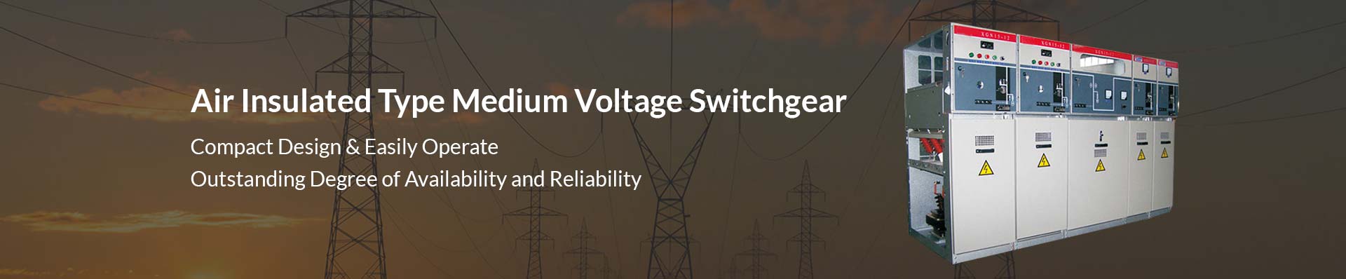
Air Insulated Switchgear
Air insulated switchgear(AIS) adopts the air as the insulation media designed voltage ranging from 11KV to 36KV medium voltage power distribution system. It plays a controlling and protecting role in the power system. The main circuit components of the air insulated switchgear are built in the gas-filled compartment.
The pressure is constant and not affected by the altitude. It is especially suitable for high altitude areas. The core components of the air insulated switchgear are load switch and fuse, with the advantage of simple structure, small size, low price, and safe power supply.
It is widely used in power distribution stations and compact substations in load centers such as residential area, high-rise buildings, large public buildings, and factory enterprises. The air insulated switchgear is a secondary power distribution device and is a medium voltage switchgear that redistributes the power of a primary power distribution device that is powered by a high voltage distribution transformer.
Compared with the traditional SF6 gas insulated switchgear, the biggest advantage of air-insulated switchgear is its more attractive environmental protection performance. It uses dry air instead of traditional SF6, N2 and so on.
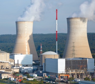
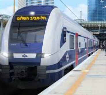
Applications For Air Insulated Switchgear


Ultimate Guide to Air Insulated Switchgear (AIS)
INTRODUCTION
In the last several years, we have seen massive development in power generation and distribution.
For the power supplier, the most vital part is the distribution and transmission control.
Because of the huge power demand brought by an increasing population and a strong industrial sector, the power supply corporation has to embrace effective methods.
One of the key areas is the substation insulation.
You see:
There are two major primary substation insulation systems around the globe.
- Gas insulated switchgear;
- Air insulated switchgear.
In this ebook, we will provide you the essential information you need to know about what is air insulated switchgear, how does it work, its components and parts, maintenance, troubleshooting and more.
CHAPTER 1: Air Insulated Switchgear (AIS) Definition: What is Air Insulated Switchgear?
The electrical substation is often ignored, yet it is an essential part of power reduction.
Irrespective of the source, electricity goes through several miles of either:
- overhead;
- underground or distribution;
- transmission lines before reaching the consumer
substations are situated along such lines.
That’s the guarantee safe electrical distribution to the consumer.
The rise in demand for electricity, as well as the growing energy density in metropolitan cities, have made it essential to extend the current high voltage network right to the consumer.
Stepping down the voltage from the transmission to the distribution level at the switchgear situated close the actual consumers not just yield economic benefits.
It also makes the sure dependable power supply.
For such reasons, a new kind of switchgear has been created.
It occupies less space, meets all the current day-requirements and is compatible along with the setting.
Air insulated switchgear of up to 800 kV have been created and are being widely employed.
What is Meant by Air Insulated Switchgear (AIS)?
The majority of industrial and utility switchgears use air to insulate live conductors electrically, and thus, are called as air insulated switchgears (AIS).
Because live conductors are prone to open air, such switchgears experience reliability issues linked with terrestrial animals, birds and weather.
Apart from thus, such switchgears feature power transformers that play a vital role in distribution system reliability.
AIS which is more typical, utilize air to insulate the various components of the substation from one another and for grounding the charge.
These kinds of substation depend on copper grounding on equipment and within the ground to ground the system properly and make it safe.
Given that this kind of system is exposed to the open environment, all elements could have a massive impact on the reliability of the components.
Classifications of Air Insulated Switchgears
If we talk about switchgear shape types, air insulated switchgear is divided in two different types:
- fixed type;
- center-mounted type
The main wiring form of the air insulated switchgear can be divided into:
- bridge type switchgear cabinet,
- single busbar switchgear,
- double busbar switchgear,
- single busbar section switchgear,
- double busbar with bypass busbar switchgear,
- single busbar section with bypass Busbar switchgear
When it comes to installation method of the circuit breaker, it can be divided into:
- fixed switchgear;
- a removable (handcart) switchgear.
On the switchgear structure, an air insulated switchgear can be divided into:
- metal-enclosed and spaced switchgear,
- metal-enclosed armored switchgear,;
- metal-enclosed box-type switchgear
Ultimately, according to the installation position of the short-circuit handcart, it can be divided into:
- floor-standing switchgear and;
- center-mounted switchgear
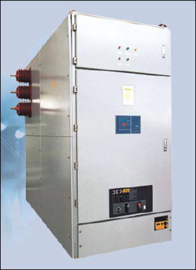
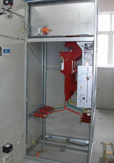
Center-mounted switchgear
Advantages of Air Insulated Switchgear
Insulated switches play a significant role in power facilities.
That’s because insulation protection is essential, large current and voltage problems with this insulation.
It is straightforward.
Good protection can ensure the safety of the line, next to its advantages.
Compared with the gas-filled insulated switchgear, air-insulated switchgear has more obvious advantages.
Because it does not inflate, it offers easy maintenance.
Insulated switches play a significant role in power facilities.
That’s because insulation protection is essential.
Large current and voltage problems with this insulation are straightforward.
Generally speaking, good protection can ensure the safety of the line.
Compared with the gas insulated switchgear, air-insulated switchgear has more obvious advantages.
That’s because it does not inflate.
It is an easy maintenance inflatable switchgear. The filling gas in the gas insulated switchgear is SF6 and N2 normally, so the maintenance cost is much higher than AIS.
Also, when transporting, bumping is difficult to avoid. If a solid object on the switchgear has cracks due to bumps, the gas will leak and it is difficult to detect. This poses a safety hazard to the use. It is better to choose air insulated switchgear in this case.
When the air insulated switchgear is installed, the outer wire first enters the main control switch in the switchgear.
Then it enters the shunt control switch to play a protective role.
When the line is overloaded, the heating element will be heated and bent, so the primary contact will be separated and cut off the power supply if there is a short circuit phenomenon or overloaded electricity.
When the flow is serious, the power supply can be cut off in time.
At present, air is a very environmentally friendly gas; there is air in all corners of the world.
For us, the advantages of them are obvious; it is worth your choice.
Air Insulated Switchgear Components and Parts
1. The surge arrester or lighting works similar to surge protectors found within your home.
When there’s too much voltage within the system, surge arresters dissipate the additional or direct it into the ground.
surge arrestor in air insulated switchgear
2. Air break switches are employed to isolate circuit or equipment within the substation.
It enables the different equipment or lines of the switchgear to be sustained with no risk of electrocution.
3. Circuit breakers, on the other hand, are automated electrical devices.
It safeguards an electrical circuit sourced by an overload on the line.
For a distribution substation use, vacuum technology is typically employed for extinguishing the arc.
It was caused by an overload within the vacuum bottle.
Other kinds of switchgear circuit breakers utilize gas or oil technology to insulate its switchgear components.
It also helps interfere with any faults.
4. The step-down transformer may be the most vital switchgear components to the AIS.
Why?
That’s because it converts enormously high-voltage power into a lower voltage.
This voltage could be transmitted down distribution lines ‘till it’s converted further by smaller transformers to practical voltage.
5. The voltage regulator keeps the right voltage after it has passed throughout the voltage regulators.
These regulators are accountable for making sure the proper electrical output travels through the distribution lines to the consumer.
6. Meanwhile, the electricity moving within the transformer is delivered to the high voltage busbar.
The bus is the junction of many various lines which distribute power in different directions.
Further, since the high voltage bus is accountable for bringing great loads, it’s yet a new piece which needs excellent care if you want to keep appropriate function.
7. Metal-clad switchgear is considered the control center for most distribution lines which leaves the air insulated switchgear.
That is where the electricity can be disbursed to specific locations with and protected with the help of the cutout switches.
It enables lines to be isolated for needed maintenance.
The word metal-clad defines the housing that the metal enclosed to safeguard the delicate equipment from the exterior elements.
In the majority of ais, utilities and engineers utilize an open-air secondary design.
It’s achieved by employing freestanding breakers as an alternative to metal-clad switchgear.
That switchgear needs more maintenance.
Thus, coops might utilize ‘reclosers’ or ‘fused cutouts’ as an alternative to switchgear to safeguard distribution circuits.
Any and all of such parts in an air insulated switchgear environment are susceptible to environmental issues.
Continued maintenance and monitoring are needed to provide reliable energy consumers safely.
Air Insulated Switchgear vs. Gas Insulated Switchgear: What’s the Difference Between GIS and AIS Switchgear?
There are wide differences between AIS and GIS.
You see: there are five significant considerations in the differences among the two HV substations:
- their construction
- installation
- operation
- continuous maintenance
- total fees of ownership
Let’s start looking at each of the differences between the two:
For Construction
In case you didn’t know yet, GIS employs the gas sulfur hexafluoride for insulation.
On the other hand, AIS employs air insulation on a metal-clad system.
SF6 is five times bulkier than air.
It provides excellent extinction behavior.
GIS system employ fixed and mounted circuit breakers.
What’s more: the sealed mounted breakers are considered a ‘sealed-for-life’ technology.
Meanwhile, AIS breaker could be eliminated for troubleshooting and maintenance.
For Installation
In case you didn’t know yet, installing a GIS can be quicker than setting up a metal-clad AIS counterpart.
That’s huge because GIS systems weigh less and smaller.
That’s irrespective of the fact that gas weighs more than air.
Presented the technician does not need to manage the gas itself.
GIS is faster to install.
AIS system requires boots and busbar connections on the switchgear.
You see, the average installation period is lessened by at least 30% with a GIS installation.
Furthermore, GIS substations take up less space compared to AIS.
For Operation
GIS is massively simpler to handle on a daily basis.
That’s because they present front rather than rear access.
They also include its incorporated testing instruments.
Arc flashes are occasional in GIS.
That’s because all other interior essentials are insulated.
The cable compartment is the only one accessible.
As the parts are entirely insulated, no linkage or cables come in contact along with the live parts.
For Maintenance
On standard, GIS systems require to be inspected visually every after four years.
That depends on the particular manufacturer suggestion for your device.
On the contrary, GIS drives to be re-greased after twenty years.
Air insulated switchgear must be inspected each year.
Once inspected, every compartment should be checked, compared to where the individual elements or compartments are wholly insulated and could be monitored.
On standard, an air insulated switchgear breaker will require four (4) hours of maintenance for every two-year time.
When we talk about the maintenance, AIS substations need more effort.
That’s true because of the meticulousness of the inspections.
Inspections include having a drawn-out, lubricate, clean, vacuum unit and a technician torque.
They also require to be checked for physical indications of copper corrosion.
That’s something which does not happen in GIS.
That’s because the units are sealed.
That sealing also safeguards the components from any environmental damage.
For Total Fees of Ownership
Ultimately, on a high-level comparison of GIS vs AIS switchgear, you should weight the upfront prices against the needed enduring maintenance.
Such units typically have a thirty-year minimum life-span.
Gas insulated switchgear is more likely to cost between ten to forty percent more than air insulated switchgear.
More Difference Between Air Insulated Substation and Gas Insulated Substation
- After the inflatable insulation, the interphase distance is only 1/3 of the air insulated cabinet, and the size of the switchgear is significantly reduced.
- Insulation medium of AIS: Using sf6, N2, and other gases or their composite gases as insulation medium, the insulation performance is strong.
- Electrical Clearance: Insulating gas insulation performance is far stronger than air, the electrical clearance of fully insulated switchgear is far less than semi-insulated cabinet
- Equipment Size: Because of the small electrical gap, the size of the air insulated switchgear is far less than the same voltage level of the semi-insulated cabinet, occupying a small area.
- Altitude effect: The main circuit components of the AIS are installed in the inflatable compartment, and the pressure is constant.
That means it is not affected by the altitude.
It is especially appropriate for high altitude areas.
The insulation performance of AIS is directly affected by altitude.
Standard products are used below 1000m.
Special design is needed for higher altitude.
Pollution effects: Contamination can’t affect the inflatable compartments of all Air Insulated Switchgear, and is suitable for polluted areas.
Semi insulated AIS is directly affected by pollution. Special harsh conditions need a special design.
To sum up, AIS substations provide open and honest cost savings.
Nonetheless, they need more man-hours over time.
The advantaged electrical engineering of gas insulated switchgear high voltage substation needs a more significant upfront investment.
However, their safe and sealed technology denotes less maintenance and installation costs.
CHAPTER 2: Air Insulated Switchgear Working Principle: How Does Air Insulated Switchgear Work?
When the line is generally overloaded, the overload current cannot make the electromagnetic release action.
However, it can make the thermal element produce a certain amount of heat.
It can promote the bi-metal sheet to be heated upward bending.
It can also push the lever to make the hook and lock off.
It can break the primary contact and cut off the power supply.
When the short-circuit or serious overload current occurs, the short-circuit current exceeds the setting current value of the instantaneous tripping, and the electromagnetic tripper produces enough suction.
The armature suction is combined with the impact lever to make the lap hook rotate upward around the rotating shaft seat and release the lock.
Under the action of the force spring, the triple contacts are cut off, and the power supply is cut off.
CHAPTER 3: Air Insulated Switchgear Installation
Connection of Main Busbars
Every busbar is linked to the Primary Disconnecting Switch.
The arrangement should be strictly followed otherwise the busbar joints will be stressed unevenly.
Make sure that the busbar mating surfaces are clean.
Then put a thin film of contact grease for the bare bar connections.
Install the interpanel busbars with the help of the proper size of nuts and bolts.
Standard Insulation Boot (OPTIONAL)
Locked “end bots” must be employed for busbar at both ends of the switchboard.
For example, red and blue phase for the left and right panels accordingly.
Lock the boots along the boot pins given.
Even boot pin should be adequately fastened to guarantee that the boot won’t drop off.
If you have a non-standard design, high voltage insulation tape should insulate any other unprotected live parts which aren’t covered along with the insulation boots.
Make sure that every joint surface is thoroughly clean and bolted before covering securely with the sealant.
The connection of the Earth Busbar
The earthing busbar links, provided with the panel are to be stable into the external earth bar in between of the panels.
Connection of Control Wings
You see: the terminals for the connection of other external wirings and auxiliary control supplies are given in the metering compartment.
On the other hand, for the control wiring connection, eliminate of the Aux Cable Bottom entry plate and Aux Cable side plate.
Control cable entry is presented at the rear and front bottom part of the panel.
After you’re done with the Control cable connection, you can now resolve the Aux cable bottom plate and side plate.
Power Cable Termination
In case you didn’t know yet, the power cable entry point is given with a removable gland plate.
It’s situated at the bottom of the cable compartments.
Standard cable entry is from the lowest.
The top entry is accessible when stated at the period of placing the order.
Inspection after Installation
Make sure that you check the door to guarantee it can be closed and opened flawlessly.
Make sure to check that every nut and bolt is bolted securely.
TAKE NOTE: Nuts and bolts are marked by the manufacturer to allow the finding of unfastened connections.
When such markets are shifted, ensure to re-tighten the nuts.
- Guarantee that every interpanel gaps are secured.
- Guarantee that every exposed busbar connecting joints are snug along with insulated boots.
- Guarantee that no loose parts or no tools are left inside the compartment.
- Clean any dust and debris outside and inside of the panels.
CHAPTER 4: Air Insulated Switchgear Preventive Maintenance and Troubleshooting
Air Insulated Switchgear Preventive Maintenance
General Maintenance
The routine inspection must be performed at regular intervals.
Inspection of AIS must be made as soon as possible after the incidence of a fault on the circuit.
The air insulated switchgear shouldn’t be put into operation with no complete test and check upon clearance of a fault.
Bear in mind that a maintenance program must be planned for the equipment.
The occurrence of the maintenance and inspection must be adjusted to consider the operating and environmental conditions, as well as faulty history.
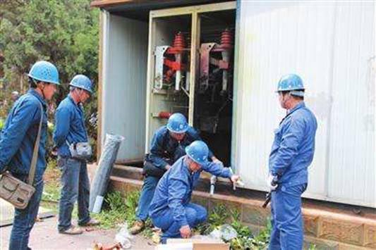
General maintenance on air insulated switchgear
Regular Inspection
Even though routine inspection is indicated, it’s possible for the maintenance staff to perform weekly checks to expect any deviations from norms after ascertaining that the AIS is stable over a period of service.
- Check the meter readings. When the readings were taken are not normal, you need to check the loads to ascertain the status.
- No covers are to be opened. The air insulated switchgear is checked externally for any irregularities.
- If an abnormal is noticed, determine the location as well as the degree of severity. You can achieve this by opening the panel door as needed. Needed safety precautions should be taken when doors are opened.
- If the irregularity is not anticipated to result in a sudden malfunction of the AIS, the concern is tracked as reference data for the next periodic examination.
- When the abnormality is anticipated resultING in AIS failure, de-energize the AIS damaged after making sure that it’s safe to do so and correct the fault.
Variants
Make sure to check on protection relay flags, meters and more.
Monitor and record meter readings as well.
Check when annunciators and protection relays have operated.
Determine and remove fault.
Reset and record.
Check on the Metal Parts
The level of peeling and rusting of paint surfaces varies on the service conditions, the environment as well as the duration of use.
Specific paint finish is accessible on request.
Throughout the periodical checks, attention must be paid to such points:
1. Peeling of paint or coating
Discoloration or peeling of paintwork might be a sign of overheating.
Employ a temperature sensor to scan such metal surfaces.
Monitor and record temperature variants.
2. Rust on metal parts
- Corroded spring and welded areas which experience deterioration in their mechanical strength.
- Rusted moving parts which don’t slide or rotate smoothly
If the ambient condition is massive, the paintwork will weaken after several years of service.
It’s suggested that such areas where the coating or paint is found to have peeled off are repainted after the rust is eradicated.
Noise Recognition
Did you know that a newly commissioned panel must work without noise?
In the long run, noise might be emitted.
It might be the noise from control, potential transformers, components or the panel.
Determine the source of that noise for needed actions.
Yearly Maintenance
Yearly maintenance is conducted with no voltage being applied and without disassembling the internal components.
All the devices must be monitored externally by touch and visual based on the inspection schedule.
When the supply of main bus power isn’t shut down throughout the inspection, you can utilize the greatest caution for safety.
At the same time, a permit to work must be delivered to the workers before the beginning of work and delayed upon its accomplishment.
Safety Precautions
Did you know that routine maintenance of the air insulated switchgear must be carried out under the management of a competent individual?
You must follow safety processes throughout the maintenance of AIS.
- Make sure that the incoming HV supply is turned off.
Remember that precaution must be taken to make sure that the incoming circuit can’t be re-energized.
- Trip the incoming supply VCB and remove it from the compartment.
- Earth the arriving cable.
- Issue a permit-to-work. Perform the following guidelines when the incoming supply can’t be turned off.
- Trip the incoming supply and withdraw it from the compartment.
- Deadbolt the shut categorized CABLE on its closed position. The key must be in the hands of an authorized individual.
- Don’t EARTH the upcoming cable.
- Make sure to suspend a warning notice and create temporary barriers at the rear and front.
Maintenance Procedures
If you want to perform the maintenance work, make sure to follow the following instructions.
Cleaning
All dirt and dust on the top cover of air insulated switchgear must be brushed off and cleaned before commencing any dismantling.
Doing this will lessen ingress of dirt into internal portions of the AIS panel.
You can employ a lint-free clean cloth to unsoiled your switchgear.
Insulation
All insulation surfaces must be cleaned and inspected for indications of blistering, treeing, tracking and delaminating or any mechanical change.
There must be no sign of grease on any area of the insulation surfaces, particularly at the tubes in the VCB compartment.
Dry and clean insulators with a proper cleaning agent.
NOTE!! Your cleaning agent can’t be employed on the grey and black surfaces on the copper bars.
Earth and Main Busbars Connections
Make sure that every connection is secure and that good contact is kept.
That examination must include opening the boots for torque checks on the busbar bolt joints.
You see: there’s a slim chance for the annual shutdown of the bus. However, checks must be done at least every three years.
Earthing Switches
Earthing switches must be tested for proper operation as well as its contacts for appropriate connections.
The proper interlocking between the VCB and the earthing switch must be confirmed.
Heater
The operation of every heater, where fitted, must be confirmed.
Secondary fuses and wiring
Make sure that all the connections are in good contact and tight.
They must be all maintained.
Confirm the continuity of the wiring to the guess, instruments, relays, instrument transformers and other connected devices.
Every contact which includes that for the socket and plug contacts must be lubricated and cleaned frugally with the appropriate lubricant.
Fuses also must be tested for permanency and assessed for indications of deterioration.
Auxiliary switches, interlocks and indicating devices
Auxiliary switches must be stored in an operational and clean setting.
That’s because they’re crucial to the proper functioning of the equipment, particularly the protection system.
Representing devices like semaphores must be assessed for proper operations and blow bulbs changed.
Locking and interlocks devices must get specific attention, particularly those linked with testing and earthing facilities.
A worn of strained out device might lead in a risky condition.
It must be confirmed that mal-operation is reserved acceptably.
Lubricate when needed.
Voltage transformers (VT) and current transformers (CT)
The step must be taken to guarantee that VT is remote and settled to earth before the beginning examination.
Care must be taken to guarantee that the transformers aren’t made live because of the response from the secondary windings.
When it comes to CT, attention is drawn to the risky voltages which may lead when the secondaries are open-circuited, and the primaries are on load at the same time.
Any connections eliminated for testing or checking must be changed and tightened securely.
Moreover, insulation resistance and stability tests of the secondary wirings must be performed where possible.
Basically, you need to check the VT and CT for physical appearance.
That all associated connections are right.
The insulation material must be cleaned and assessed carefully for any indications of damage like peeling, tracking marks and cracks.
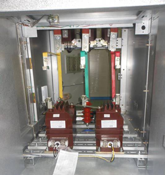
Voltage transformer in air insulated switchgear
Protection relays
Clean off any dust on the relay covers before you remove them.
Make sure that the covers are changed carefully to lessen the entrance of dust into the relays.
Addition testing by primary infection is preferable.
Nonetheless, regular testing by secondary injection is enough to prove the reliability of the relays.
Tests must be done on protection relays to confirm the resetting and operating times, the drop-off and pick-off values.
In the case of the electromechanical relays, utmost care must be done to prevent damage to the relay devices if working the induction disc of the relay.
Generally, prevent subjecting protection relays to HV tests.
When such tests are needed, make sure that the proper tests voltages are employed which such connections are restored before the switchgear go back into service.
Control relays or contractors
Check mechanical parts for free movement along with the control and main circuit isolated.
You can also check the operation of the contractors or relays through energizing the control circuit.
Batteries, transducers, and meters
For the following items, you can refer to the relevant instruction manuals of the manufacturer presented for operation checks:
- DC control supply/tripping
- Transducers (var, watt, current, voltage)
- Energy meters (reactive or active)
- Ammeters and voltmeters
- Protection relays
Shutters
The isolating contacts must be assessed for deformation and discoloration because of environmental contamination or overheating.
Replace if needed.
Change conductors if the cause is overheating.
If it suffered from environmental contamination, remove the source and clean the plating surface along with the proper cleaning agent.
Air Insulated Switchgear Troubleshooting
You must be aware that air insulated switchgear is created under strict quality control.
It also had undergone a routine factory test before it was dispatched from the factory.
Nonetheless, must any defects be discovered during regular inspections, make sure that you investigate the origin of trouble.
1. Handle can’t be locked
The possible cause for this problem might be the internal mechanism rusted, you use the wrong key, or the internal mechanism is faulty.
To fix this problem, make sure that you check your key number. You can also lubricate the hole or when an emergency, cut off your handle.
2. Internal noise
Does your air insulated switchgear produce an internal noise?
The cause of this might be because of the electromagnetic induction screws on the partition plates.
It might also be because of the cable touching the gland plate.
You can easily resolve this problem by retightening your screws or adding a sealing compound between plate and cable.
3. Ground fault or failed dielectric tests
What about failed dielectric tests?
The reasons for this problem might be rooted in the cracked insulators, the insulators stained with foreign moistures and matters or it might be an intrusion of rodents.
But don’t worry, the solution is straightforward.
You can either replace insulators, dry and clean insulators along with an appropriate cleaning agent or plug openings and gaps to remove rodents.
4. Shutters can’t open
The primary cause of this would the padlock is left locked on the shutters; moving parts are poorly adjusted, and the lubricating oil is deteriorated, or the shutter is deformed.
You can easily troubleshoot this by unlocking the padlock, adjust the moving parts and put lubricating oil and repair deformed shutters accordingly.
5. Shutters can’t close
Damaged shutter might be the possible cause of this problem.
To fix this, you can repair the damaged shutters, clean the moving part, or adjust the moving parts and put some lubricating oil.
6. Poor operation of the control units
There are two probable roots for this issue.
One would be the unfastened screws on the terminal blocks.
Second, the control circuit plug isn’t connected correctly.
To fix this, you can re-insect the control circuit plug or re-tighten the screws on the terminal blocks.
7. Extinction of the indicating lights
There are several causes of this AIS problem.
They are the following:
- Limit switch contact removed or faulty
- Auxiliary supply switches open dispersed
- Poor contact of auxiliary switches at the breaker
- Resistor or fuse burnt
- Bulb filament is broken
To fix this, you need to do the following:
- Assess the limit switches contact and operation of the limit switch
- Monitor MCCB of the wire and fuse terminals
- Clean the auxiliary contacts
- Replace resistor or fuse
- Change bulb
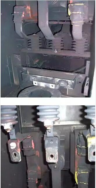
Air insulated switchgear inner trouble
8. Connections overheated
The two causes of this faulty are due to overhead and loose bolts.
The simple way to fix this is by limiting current to the rated value and by re-tightening bolts to given torque or change busbar if needed.
Conclusion
There is no doubt that air-insulated switchgear is a vital feature for any electrical system.
Without an efficient switchgear situation, the electrical system is not stable and not safe.
Now that the Air Insulated Switchgear technology can operate through remote control, the safety of the situation has been raised significantly.