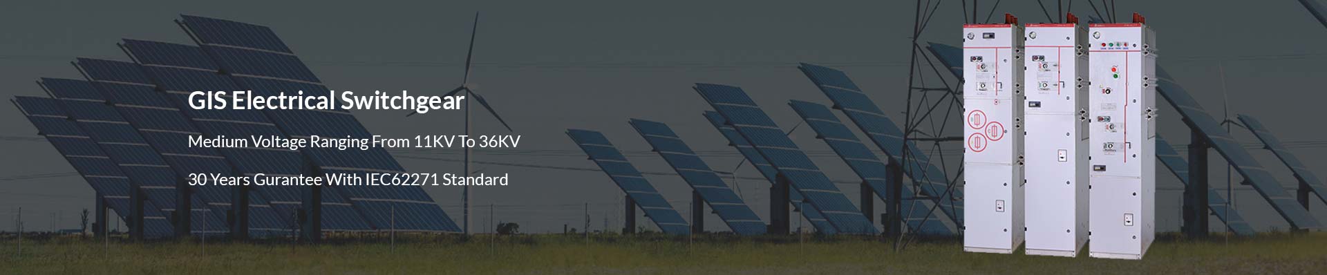
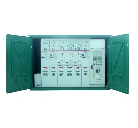
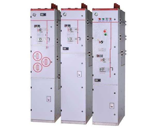
SF6 Gas Insulated Switchgear
As one of the leading manufacturers of medium voltage SF6 gas-insulated switchgear(GIS) in China, Orecco designed the gas-insulated switchgear for the secondary voltage distribution network in 6 different configurations. s is suitable for most switching applications in 11KV/33KV secondary distribution networks.
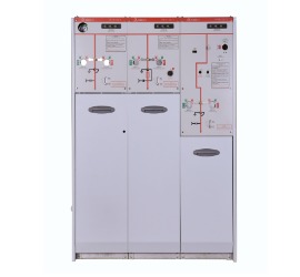
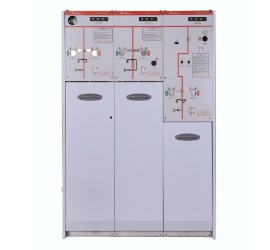
S SF6 gas insulated switchgear is a new generation medium voltage switchgear. The entire SF6 gas tank sealed high-voltage components such as busbars, circuit breakers, disconnectors with 1.4bar pressure SF6 gas in IP67 protection degree.
So all of the live parts inside worked in the full sealed tank without causing any problem even the switchgear was flooded with water. This SF6 gas insulated switchgear working principle is the biggest advantage in the working stability and development of miniaturization and it also without any maintenance for 30 years time.
SF6 gas insulated switchgear(GIS) has vacuum circuit breaker and disconnector without maintenance, which greatly reduces maintenance and inspection workload.
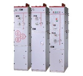
Applications For Sf6 GIS Gas Insulated Switchgear

SF6 Gas Insulated Switchgear Basics: The Definitive Guide
Are you planning to purchase a gas insulated switchgear?
After that idea pops into your mind, you are now faced with a dilemma.
You’re now asking yourself a question, “How can I be smart enough to purchase a gas insulated switchgear?”
The good news!
With this e-book about Orecco, we will provide you with everything you need to know about SF6 switchgear!
Yes, you read that right!
Here, you have the best tool right in your hands!
Use this guide to equip yourself with all the information you need!
Do you think we’re overstating?
Well, there’s only one way to be certain.
And the answer lies in your hand.
Start reading today to find out!
- Gas Insulated Switchgear (Gis) Definition: What Is Sf6 Gas Insulated Switchgear (Gis)?
- The Purpose Of Gas Insulated Switchgear: Why We Use Gas Insulated Switchgear?
- Gas Insulated Switchgear Working Principle: How Does Gas Insulated Switchgear Work?
- Gas Insulated Switchgear Design & Drawing
- Gas Insulated Switchgear Testing Procedure
- How to Install Gas Insulated Switchgear: Gas Insulated Switchgear Installation Procedure
- Gas Insulated Switchgear Maintenance
- Gas Insulated Switchgear Troubleshooting: Simple Analysis about the Technical Problem of SF6 Gas Insulated Switchgear
Chapter 1: Gas Insulated Switchgear (GIS) Definition: What Is Sf6 Gas Insulated Switchgear (GIS)?
The gas insulated switchgear manufacturers market is among the major industries serving the global power sector.
In coming years, the switchgear industry is anticipated to show massive growth.
The demand for power in the upcoming industries and the substantial rural electrification drive is poised to keep the switchgear industry busy.
In this field, technology is the fundamental resource.
SF6 Gas insulated switchgear
But why is that?
It’s because most multinational gas insulated switchgear manufacturers are key players in the switchgear industry.
They have access to source technology.
Nevertheless, in the coming years, many corporations are anticipated to upgrade their technologies.
They are anticipated to develop gas insulated mv switchgear products to serve the ever-growing power market.
It’s worthwhile to understand what gas insulated switchgear means before you move to how does switchgear works. We will also discuss the advantages of gas insulated switch gear.
In this chapter you’ll know about gas insulated switchgear basics and gas insulated switchgear working principle.
What is a Gas Insulated Switchgear?
GIS is a compact form of switchgear. The full name of GIS is Gas Insulated Switchgear.
The size of the gas insulated switchgear medium voltage lowers massively because of the use of SF6 (Sodium Hexafluoride) insulation.
There are many advantages of gas insulated switchgear. And this product is commonly utilized in high and medium voltage application.
You might be wondering:
SF6 gas insulated switchgear is more compact, maintenance-free and safer compared to AIS.
The durability of gas insulated switchgear construction is higher than AIS as well.
In C-GIS, the majority of the live and current-carrying components are sealed in SF6.
Continuous atmospheric conditions in the sealed tank enhance the performance of the switchgear.
When we talk about the basics of gas insulated switchgear, the design is the most vital aspect.
Most multinational corporations have developed this product in their technology centers.
In some countries, designing gas insulated switchgear types isn’t accessible easily.
While designing a gas insulated switchgear presentation, a designer must look at crucial aspects such as:
- Maintenance-free mechanisms
- Over-pressure sustaining capacity
- Leak-proof joints
- The overall performance of all components
In this gas insulated switchgear types, all the needed components can be assembled in a limited space.
Also, C-GIS is considered as gas insulated metal enclosed switchgear.
That means:
The gas-tight metal enclosure encloses all the equipment of the electrical switchgear.
SF6 gas insulated switchgear is utilized as insulation between the earthed metal enclosure and live parts of the equipment.
This type of switchgear is accessible from 12 KV systems to 800 KV systems.
This type of SF6 insulated switchgear plays a crucial role in establishing an electrical substation in very limited space.
That’s the working principle of gas insulated switchgear.
Gas insulated switchgear medium voltage components of substations are typically:
- Earth switches
- Lightning arresters or surge arrestors
- Voltage transformers
- Current transformers
- Circuit breakers
- Disconnectors or electrical isolators
- Electrical bus bars
What’s more:
The compactness of gas insulated mv switchgear has a direct influence on land cost and land requirement.
Compact modular designs provide countless possibilities in layout design. It also enables tailor-made applications.
Gas insulated switchgear construction is preferred in:
- Valley regions and mountains
- Offshore
- Power plants and substations located
- Heavily contaminated saline environment
- Underground stations
- Major towns and cities
On the other hand:
The substation collected by gas insulated mv switchgear is called as GIMES (gas insulated metal enclosed substation).
This technology isn’t a recent invention, as it’s running for more than 30 years successfully.
Many gas insulated switchgear manufacturers have also created their own product.
In gas insulated switchgear medium voltage, vacuum technology is utilized as interrupting use.
SF6 gas is utilized as insulation material.
Even though for both insulation and interruption, SF6 gas insulated switchgear is utilized in countless medium voltage GIS system.
However, for equipment rated SF6 gas pressures are diverse for insulation and interruption.
As it turns out:
SF6 gas pressure for the insulating use is preserved below 2.5 bars while SF6 gas pressure for interrupting purpose is ranged from five to seven bar.
Also, as vacuum technology isn’t accessible for high voltage, so for C-GIS system above 72.5 KV, only SF6 is utilized both for insulation and interruption medium.
Gas Insulated Switchgear Types
By the way:
There are also different types of gas insulated metal enclosed switchgear accessible.
It solely depends upon their constructional features.
1. Isolated Phase GIS
With this configuration, every phase of the bay is gathered individually.
Simply put:
For every phase,
- one (1) pole of the circuit breaker,
- one (1) phase assembly of the current transform, and
- a simple pole of an electrical isolator
are assembled. Isolated Phase GIS needs bigger bay than other gas insulated switchgear systems.
Meanwhile:
2. Integrated Three-Phase GIS
In this gas insulated switchgear type, all three phases of the circuit breaker are encapsulated in a single metal enclosure.
It’s composed of three phases of current transformers and three phrases of disconnectors.
The organization creates a three-phase module for the element.
As it turns out:
The size of this module is one-third of Isolated Phase GIS.
3. Hybrid GIS System
On the other hand, we have the Hybrid GIS System.
This type of gas insulated switchgear is a suitable mix of three-phase common elements and isolated phase.
Here, three phase common bus bar system shortens the connection from the bus bar.
You see:
The isolated phase equipment stops phase-to-phase faults.
It’s an optimum design considering both maintenance facility and space requirement.
4. Compact GIS
Lastly, in this GIS system, more than single functional elements are condensed in a one metal enclosure.
For instance:
In some designs, current transformer, a three-phase circuit breaker and earth switches and other feeder elements are covered together with a one metal capsule.
5. Highly Integrated System
In case you didn’t know yet, this design was released in 2000.
In that year, total substation equipment is encapsulated altogether in one enclosure housing.
The single gas insulated metal enclosed switchgear has obtained user appreciation.
That’s because it’s a total solution for an outdoor substation, in one unit.
As such, only HIS is an alternative to a complete outdoor switchyard.
Gas insulated mv switchgear technology provides a lot of benefits and gas insulated switchgear advantages which are harder to quantify.
But it can be conclusive for the realization of a project.
One instance is the complete integration of GIS substation in a current building – if no additional site area is accessible.
Think about it:
SF6 gas insulated switchgear is a flexible, cost-efficient, reliable and eco-friendly solution for supply systems.
These are perfect in places with high load densities.
Even though it appears to be more expensive, its compact modular designs.
It provides a lot of possibilities in layout design.
That results in a massive saving in investment and operating costs which more than compensates for the added costs of the GIS.
Hopefully, you have now better understand what gas insulated switchgear means and how does switchgear work.
Chapter 2: The Purpose Of Gas Insulated Switchgear: Why We Use Gas Insulated Switchgear?
Now, you are fully aware that the GIS system primarily utilizes Sulphur hexafluoride gas as its main insulator.
The SF6 keeps molecular and atomic properties even at high voltages, superior arc quenching, and high cooling properties.
SF6 also has superior dielectric properties than other gases.
So what does it mean?
It offers significant insulation for the phase to ground and phase to phase moderation.
In this chapter, we’ll discuss the benefits of gas insulated switchgear.
Learn more about SF6 gas insulated switchgear function.
There are many challenges in today’s power transmissions.
One of them is to bring extreme high voltage levels into the centers of urban areas.
That requires switchgear which features:
- The utmost reliability
- A small footprint
- Electromagnetic emissions
- Very low noise
Luckily!
The application of gas insulated switchgear is suited to meet such requirements.
And thanks to its compact design, GIS needs a very small space.
The benefits of gas insulated switchgear are the following:
- Fast assembly because of extensive pre-assembly. Fast site assembly guaranteed by comprehensive pre-assembly to low-cost buildings and foundations.
- Under scheduled maintenance, SF6 doesn’t age and depletes.You don’t need to top up the gas levels through the equipment lifetime.That’s approximately 40 years!Isn’t that amazing?
- Low maintenance needs.That’s because it features protection and expedient design against external elements.
- It features a compartmentalized enclosure of the live parts.That makes for a very dependable system because of disruption of the insulation system.
- The earthed metal enclosure creates for a safe working setting for the attending personnel.Let’s explain how this works:Gas insulated switchgear is safe.How?The earthed metal enclosures secure operating personnel.
While the switchgear is in operating condition, the personnel can safely touch the compartment.
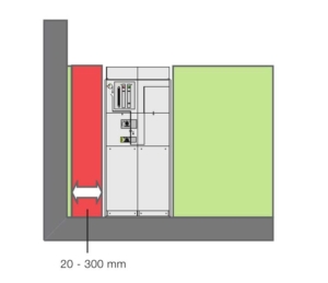
- Did you know that switchgear lessens the distance between active and non-active switchgear parts?Less space is needed in the standard AIS system.That comes in handy in compactly populated places and unfavorable terrain.In fact:The installation of SF6 switchgear takes up at least 10%.
That’s the only amount of space needed for the conventional installations.
- It offers low weight benefit. That’ because of the aluminum enclosure.That corresponds to low cost buildings and foundations.
A point of note is that gas insulated switchgear has the same compartments as the normal setups.
The major difference is only the insulated medium and the size.
The live parts and compartments are insulated in metal enclosures.
It’s filled with SF6 gas at a reasonable temperature.
Every compartment housing the live part is a gas tight.
That guarantees that the gas doesn’t pass to the neighboring models.
It’s to guarantee as well that gas monitoring is independent and simpler.
‘O’ rings are set up at the equipment and enclosure flanges to offer the gas tightness.
Application of Gas Insulated Switchgear
In the standard setup, the space between ground to phase and phases are quite big.
That’s where the standard AIS come in handy.
Nevertheless:
With the growing number, particularly the big cities and towns, such big spaces are tough to come by.
Luckily:
That’s where the gas insulated switchgear function is mot application.
The gas offers superior insulation properties instead of air.
Simply stated:
The substation unit can be enclosed in a smaller area with gas insulated switchgear fire protection.
The usage of the SF6 lessens the space between the ground the phase and the phases.
Further, the:
- Whole substation and;
- Size of the equipment
Can be lessened by at least 10%.
It’s the substantial area if you consider the size of gas insulated substations serving big towns and cities.
But wait, there’s more!
Roughly, 80% of the yearly consumption of SF6 is utilized for GIS equipment.
Of the 80%, the medium voltage switchgear accounts for about 10%.
In both electrical applications, the equipment is made to include the gas in the enclosed pressure system.
These are assembled, filled and tested in a controlled setting.
Check this out!
Other area application of gas insulated switchgear are the following:
- Highly populated places
- Substations located in rough terrains like valley and mountain regions
- Offshore-situated substations
- Underground station. It lessens the total area to be excavated.
It leads to cutting costs.
No doubt about it!
Switchgear plays a crucial role in the reliable and safe distribution of electrical power.
Failure to disconnect faults efficiently downstream in the network is costly.
That results in:
- Damage to equipment
- Loss of supply
- Possible injury to the operating personnel
Therefore, it’s critical that switchgear is picked, installed, operated and maintained properly.
It should embrace an overall asset management regime, which is both:
- effective and;
- economic
in securing an extreme level of system reliability.
Let me take a wild guess.
For both technicians and engineers out there, gas insulated switchgear offers the best.
For most gas insulated substation projects around the globe, gas insulated switchgear function provides apparent merits.
That’s because of the economic and technological benefits of gas insulated switchgear.
Chapter 3: Gas Insulated Switchgear Working Principle: How Does Gas Insulated Switchgear Work?
After understanding the benefits of gas insulated switchgear, what’s next?
Those, are just a few.
But wait, there’s more!
In this chapter, we will guide you on how gas insulated switchgear work.
Allow us to walk you through the entire process:
You see:
Gas insulated switchgear configuration is categorized based on its interruption technology.
It’s the strategy by which it quenches its electrical arc.
Using the categorization, there are five types of switchgear accessible in the market today, and these are:
Oil circuit breaks – They vaporize oil to send a jet of oil with an arc
Gas (SF6) breaks – They stretch an arc and depend on the SF6 to extinguish it
Vacuum Breaks – They extinguish their relatively small arc through extending it
Air Breaks – They normally utilize a puff of air to extinguish an arc
Hybrid Breaks – Utilize more than one kind of breaking technology to extinguish an arc, like air or gas.
Gas insulated switchgear configuration generally composes of protecting and switching devices.
These are:
- current transformers
- lighting arrestors
- control panels
- relays
- circuit breakers
- isolators
- fuses
- switches
- potential transformers
- various associated equipment
Some equipment is made to work under both normal and irregular conditions.
Some equipment is intended for switching and not sensing the fault.
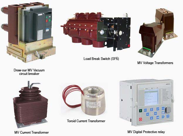
Gas Insulated Switchgear Equipment & Components
Gas insulated switchgear inside components
Gas insulated switchgear with vacuum circuit breaker is composed of a wide array of equipment.
These are concerned with interrupting and switching currents under both regular and irregular conditions.
It includes relays, circuit breakers, fuses, switches, and other equipment.
Relays
A relay is a device that senses the fault.
It also supplies the information to the breaker for circuit interruption.
Circuit Breakers
This is equipment that can close or open a circuit under all conditions.
It’s built so it can be run manually under regular conditions.
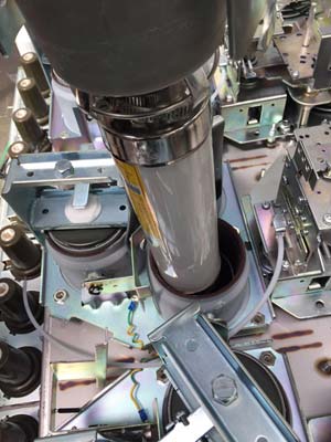
Vacuum circuit breaker
Fuses
A fuse is a small piece of wire that melts when extreme current flows through it for enough time.
Fuse
It’s attached in a series with the circuit to be secured.
Switches
A switch is a mechanism that is utilized to close or conveniently open an electrical circuit.
It can be utilized under no-load or full-load conditions.
However, it can’t disturb the fault currents.
Gas insulated switchgear technology has reached a stage of application.
And the wide array of GIS equipment is accessible with different unique features.
How Does Gas Insulated Switchgear Work?
The so-called inflatable cabinet is to seal high-voltage components such as:
- busbar;
- circuit breaker;
- disconnector and;
- Transformer, etc.
in the shell filled with low pressure (0.1-0.5mpa) SF6 or other gases.
Its working principle is similar to an electromagnetic relay.
You see:
With the use of permanent magnet mechanism, the cabinet is full of insulated air and sulfur hexafluoride gas compartment combined.
It ensures the structure is compact and has strong ductility.
It also has a good application in sensing technology.
Its appearance makes some high-voltage current work no longer dangerous.
The performance-price ratio for using this kind of insulated switch is still very high.
It has strong practicability as well.
Compared with the general products, it uses a metal enclosed structure, after a series of special processing has higher accuracy and good corrosion resistance.
It can guarantee the normal use of different environments.
In the process of using solid insulation materials for each live component, the elements can be switched flexibly to achieve good results without contacting the live component.
Compared with the general equipment, it has:
- shielded grounding, s
- safe use and other characteristics
The launch of the market has been favored by the public.
The function of Each Part of Gas Tank
There is two functions of each part of the gas tank, and they are:
1. Integral Switch
The integral switch can be composed of:
- disconnector switch,
- circuit breaker switch,
- grounding switch,
- load switch and;
- grounding switch, or load switch,
- grounding switch;
- and high voltage fuse.
According to the needs of users, we choose different integrated switches.
The combination of various switches greatly:
- reduces the volume,
- eliminates the interlock between switches, and;
- has better stability.
2. Bushing
As the connection between the internal switch and external power supply, the bushing should have:
- good performance,
- enough load capacity and;
- air tightness.

Cable bushings
3. Dynamic Sealing Components
Dynamic sealing components are also called cooperation.
It’s an integral switch and the operation structure of the connection; the operation mechanism operated outside.
Through the sealing components, it will transfer the action to the internal switch, to achieve operational functions, while ensuring the sealing.
4. Explosion-Proof Valve
Explosion-proof valve is an outlet hole reserved for the gas tank of the inflatable cabinet.
That’s sealed under normal conditions.
What’s more:
The sealing material is not strong enough for the gas tank of the inflatable cabinet.
When the switch fails to heat up, the temperature rises and the internal pressure rises sharply.
Further:
When there is not a relief port, the whole gas tank is easy to burst, and the loss is serious.
Take note:
The explosion-proof valve is designed to prevent the preset vent of the airbox explosion.
5. Operation Structure
Finally, we have an operation structure.
The operation mechanism of the inflatable cabinet can be divided into:
- manual and;
- electric operation.
The electric operation structure can realize the “three remote functions.”
The operation mechanism can be connected to the internal switch through the dynamic sealing component.
Thus it plays the operation function.
During standard operation, gas insulated switchgear configuration allows to switch on or off:
- transmission lines
- Generators
- distributors, and;
- various electrical equipment.
On the contrary, when a failure happens on any part of the power system, a huge current flows through the equipment.
It threatens damage to the equipment and interruption of service to the users.
The switchgear notices the fault and disconnects the unhealthy region from the system.
The switchgear equipment is concerned essentially with interrupting and switching currents either regular and irregular operating conditions.
The tumbler switch along with standard fuse is the simplest form of switchgear.
It’s utilized to safeguard and control lights and other equipment in offices, homes, etc.
Chapter 4: Gas Insulated Switchgear Design & Drawing
There’s fast development of the local economic construction.
But the urban power grid load is much higher than ever.
The urban power supply is gradually developing to the ring type power supply mode.
Along with its special advantages, the ring network power supply technology has been widely utilized in the distribution system.
Did you know?
It plays a role in controlling and protecting the distribution system.
You are already aware that SF6 fully insulated switchgear is low-pressure gas insulated.
It features an arc extinguishing medium switchgear.
It offers:
- More reliability
- Compact structure
- Maintenance free
- Easy to expand and so on.
It’s widely employed in China due to its excellent advances in a flexible combination like:
- Terminal power switching equipment and;
- Power supply
Gas Insulated Switchgear Structure
SF6 gas insulated switchgear can be categorized into nine basic types according to their uses.
So let’s take a closer look at each of them.
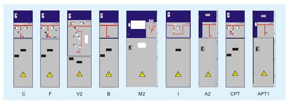
9 Kinds of Basic Cabinet of Full Insulated Switchgear
1. APT1 (APT1)
Along with the load switch PT cabinet, it can drag motor lighting equipment.
These gas insulated switchgear spare parts are easy to maintain and overhaul.
2. CPT (CPT)
This pressure change cabinet is for air insulation.
The minimum capacity of PT is 5000VA, where you can drag motor lighting equipment.
3. Cable Introduction Cabinet (A2)
Here, the air insulated cable connector is connected directly to the busbar.
It also has a metal protection shell.
This part is mainly utilized in the outline of the cable into the line.
4. Cabinet (I)
This gas insulated switchgear standard is utilized mainly in 2-stage bus segment and contact.
5. Metering Cabinet (M2)
The air is insulated. It’s mainly utilized in the power supply department of line metering.
6. Cable Introduction Cabinet (B)
You see:
The SF6 gas is insulated, and the higher pressure region is located in the Sf6 gas.
Cable introduction cabinet is mainly utilized for the introduction of cable entry.
7. Circuit Breaker Cabinet (V2)
Circuit breaker cabinet can’t be only applied to:
- Control
- Segment
- branch
- Cable connection
But also, circuit breaker cabinet can be applied to the following:
- Big capacity distribution transform control and;
- Protection of larger capacity distribution transformers
Transformer protection
8. Load Switch + Fuse Combination Electric Cabinet (F)
This gas insulated switchgear structure is mainly utilized in two (2) distribution network capacity of 1250kVa.
It controls and protects the two terminal distribution transformers with a capacity below 1250kVa.
F Module Design
9. Load Switchgear (C)
Gas insulated switchgear standard load switch cabinet is mainly utilized in:
- Connection
- Branch
- Segment and;
- Control of outgoing and incoming cable lines
C Module
Significant Features of Gas Insulated Switchgear Structure
Gas insulated switchgear structure needs low maintenance operation throughout its overall lifetime.
Cabinet Body Structure
It involves various main components that are designed for standard operation for over 30 years.
Do you want to know the other features of gas insulated switchgear spare parts?
So, here we go again.
Complete Shielded Cable into the Outgoing Line
Switchgear includes a standard for cable connection and standard cable sleeve.
These two are both reliable and easy to install.
Do you want to avoid the long-term use of your gas insulated switchgear?
The gas box respiration caused by the shift of temperature difference results in the weld fatigue cracking.
Laser welding
Pressure Resistance Under Zero and Five Surface Pressure
Switchgear wiring diagram can still guarantee that the equipment insulation and breaking performance is in regular use.
That’s especially true even if there’s a leak or leakage to zero-gauge pressure.
But it doesn’t just end there!
High Insulation Performance
You see:
The gas box adopts import.
3mm stainless plate laser welding is achieved to guarantee that the equipment in operation offers anti-corrosion and resistant to impact.
The airtightness of the switchgear wiring diagram is excellent as well.
You can guarantee that it will not leak for many years.
Modular Design
Modular design is adopted in the switchgear wiring diagram.
In fact, the basic module unit is load with the switch module.
The Size of the Cabinet is Relatively Small
The usage of a three-station rotating load switch offers benefit.
What is it then?
That’s because it effectively lessens the number of gas insulated switchgear spare parts.
It also lessens the realization of the mechanical interlock.
Further, the vacuum circuit breaker is equipped with SF6 insulated gas.
It is done to build the overall structure more compact and robust.
Because of the miniaturization development of the current-limiting fuse, the combination of the cabinets gets smaller.
Fully Insulated and Fully Sealed
Are you still with us?
All high-voltage charged parts of gas insulated switchgear are sealed at the low-pressure SF6 gas tank.
Thus, it is not affected by the external environment.
Some of these are:
- Small animals
- Salt mist
- Filth
- Damp and more
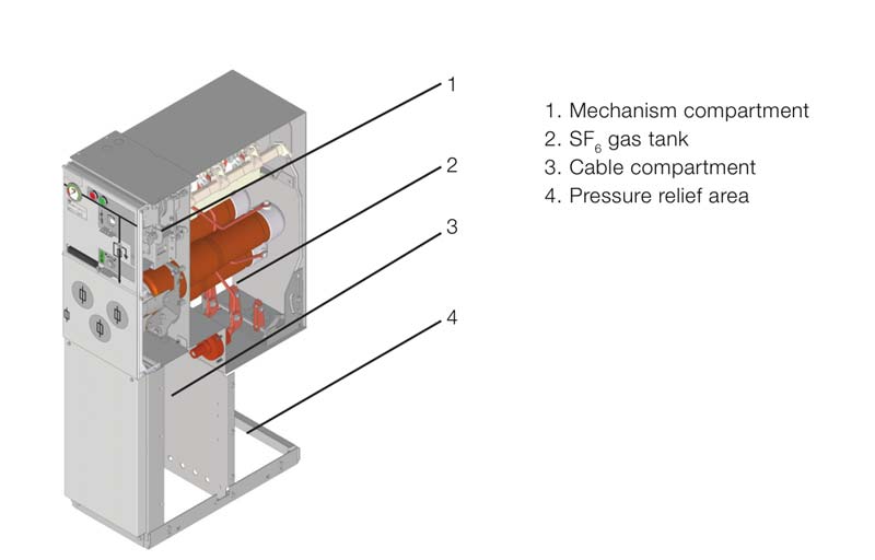
Structural Characteristics of Sf6 Gas Insulated Switchgear
The structure of the SF6 gas insulated switchgear standard is divided into different major parts.
It involves:
- Pressure relief channels
- Frame
- Cable room
- Control room and;
- Inflatable sealed box
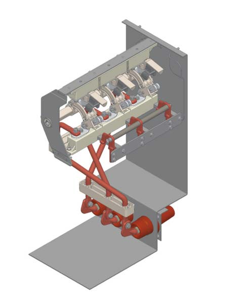
The high-voltage main circuit is situated in the inflatable sealed box.
The body chamber is located above the front.
The cable room is positioned below the front.
Lastly, the pressure relief channel is situated at the bottom.
Part Structures of Gas Insulated Switchgear
Five Anti-Mechanical Interlock
Load switch cabinets, ring network cabinets and the combination of electrical cabinets are dependable mechanical interlocking.
The principal switchgear wiring diagram has a switch state of instruction.
It must be in accordance along with the operating processes needed to carry out:
- only when the door is closed, then the grounding switch could be operated
- only when the grounding switch is in the grounding position, that’s the time the door can be opened
- only when the grounding witch is in the gate position, then the load switch can perform the closing operation
- only when the load switch is in the place of the gate, then the ground switch can perform the closing operation
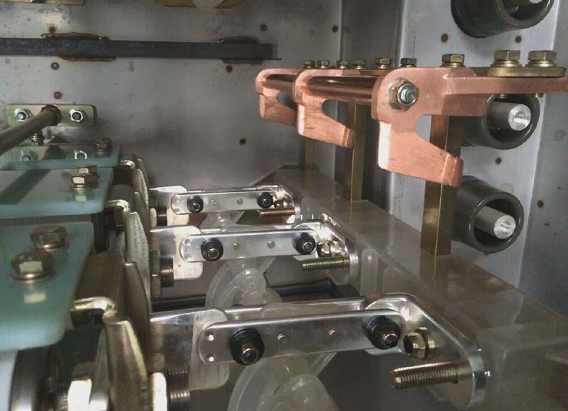
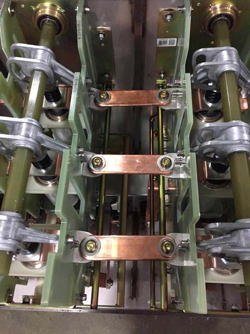
Busbar Connector
On the other hand, the busbar connector is composed of 3 silicone rubber connectors
These connectors are arranged in the middle of:
- the horizontal cone casing and;
- the side of every cabinet to be connected.
It offers continuity for the busbar and closes the junction.
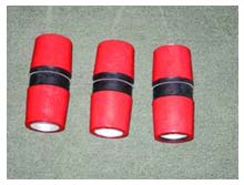
Busbar Connector
With the connector, the busbar can opportunely be connected without changing the SF6 gas.
It will not only avoid partial discharge and guarantee insulated characteristics.
It can also endure the switch cabinet that may have to short-circuit current.
Grounding Circuit
Grounding circuit separates the cable room 5x30mm2
The main grounding copper row is found throughout the arrangement for the direct grounding of the components utilized.
Further, the grounding touch seat of the 3-station load switch is linked by the copper row to the main ground copper row.
It creates the grounding loop circuit, so the whole switchgear is in excellent grounding condition.
It will guarantee the safety of the operating personnel.
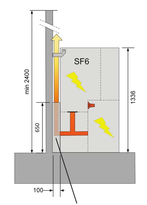
Pressure Relief Device
The pressure relief channel in the lower area of the sealing box is geared with explosion-proof methane.
It’s provided in case internal arc failure take place.
The high-pressure gas within the sealed box can burst the explosion-proof membrane.
Thus, it will release the pressure, and the SF6 gas will be discharged into the trench through a pressure relief channel.
You see:
The job of the pressure relief channel is to guarantee the safety of the operator.
Fair enough, right?
Cabinet Frame
The cabinet frame is the base of all the part assembled in gas insulated switchgear structure.
Why is that?
That’s because it holds and supports the sealing box.
Various bending forming picks the aluminum-zinc plate.
It’s connected by high-strength bolts, rivet nuts, and nuts.
The rack can be separated into three major components:
- pressure relief channel
- control room
- cable room
Fuse
The fuse and load switch build the transformer protection circuit.
That’s the time when the high interruption current limiting fuse is installed on the insulated shell of the epoxy casting.
If a fuse breaks down when a short circuit happens, the firing pin pops off the load switch.
It causes the load switch to break the circuit, so the fault line is eliminated.
A spring impactor is utilized for the fuse impactor.
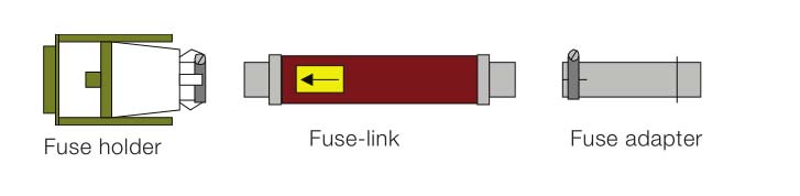
Fuse link
Fuse Grounding Switch
In the combined electrical cabinet with the load switch + fuses, the fuse grounding switch is installed with 3-station load switch.
These gas insulated switchgear spare parts offer solid grounding to the fuse end.
If the load switch is closing and opening operation, the fuse grounding switch doesn’t act.
When the load switch is attached to the ground, the fuse is grounded.
Simultaneously, the movement is dependably contacted with the static contact base of the fuse outlet.
That is to guarantee the fuse.
Three Position Load Switch
The load switch attached to the inflatable shell is considered a three-station load switch.
It has three positions of grounding, opening, and closing.
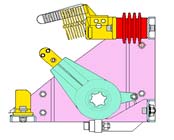
Three Position Load Switch
If the moving blade is in the place of the gate, it provides enough insulation distance.
The grounding switch and main switch can be closed and separated along with one operation handle.
Meanwhile, there’s a mechanical interlock between the grounding switch and main switch.
Sealed Box
The gas box is loaded with SF6 gas.
It uses fully welded sealing technology and synchronous vacuum helium leak detection.
It doesn’t require to be inflated during the complete life cycle to keep safe operation.
The technical features of SF6 gas insulated switchgear standard gas insulated switchgear are very apparent.
That’s the main reason why it was integrated into many new technologies.
This includes:
- Sensor technology
- Control technology
- Insulation technology
to name a few, which are known to grow rapidly.
Chapter 5: Gas Insulated Switchgear Testing Procedure
At present, gas insulated switchgear components control panels are tested manually by utilizing the following methods:
- Continuity tested to check connections
- Utilize toggle switches and sorting links to short terminals on the socket and check if the control panel:
- Generate alarms and;
- Show proper indications and more.
In this chapter, we will tackle gas insulated switchgear technical specification.
So, let’s get started.
General Examination
1. Appearance Structure
The height, width, and length of the vacuum switchgear must comply with the designs of gas insulated switchgear specification.
The diagonal error must not go beyond 3 mm.
The protection grade of the voltage switchgear must be in accordance with the IP2X requirements.
It includes the:
- Top
- Front and;
- Rear
That is round copper along with a diameter of twelve millimeters.
It must not enter its inner copper rod.
If not, over four places aren’t needed to be judged to be unqualified.
On the other hand, the hoisting crews must conform to low voltage switchgear specification.
There should be no cracks and other quality concerns.
Installation must be sufficient and firm as well.
What’s more:
The welding of the net door must be smooth and firm.
There must be no partial shedding or protrusion.
The opening holes of the installation holes must be standardized and correct.
The bolts utilized for assembling the screen cabinet must be geared with spring washers.
It should not be locked too.
Take note:
All the door switches should be free from jamming and flexible.
The opening angle must not be less than ninety (90) degrees.
The grounding point of every door must be connected.
You see:
The color mark of cabinet spraying should meet the requirements.
It should not have any apparent color difference.
But why is that?
There must be no stains, paint, or scratches dropping on the surface of the cabinet.
2. Sign, Phase Sequence Check
The main circuit phase sequence must be correct.
The main grounding sign must be precisely and tightly.
The gas insulated switchgear specifications and switchgear components in the gas power system must be in accordance with the gas insulated switchgear specification requirement of the manufacturing medium voltage switchgear specification.
The number must be in accordance with the low voltage switchgear wiring diagram.
The position must be organized according to the left, right, lower and upper orders of the
medium voltage switchgear components parts.
The operation labels must be attached correctly, firmly, and neatly.
The installation of product nameplates must be standardized and level.
What does it mean to you?
That denotes all the contents must be marked correctly and clearly.
The production of analog lines must be consistent along with a manufacturing gas insulated switchgear specification.
The production must be beautiful and neat too.
It must be consistent, before making the ac switchgear, it must be wiped.
After production, it must be roasted solid.
Primary Loop Check
The primary circuit connection must follow to the design gas insulated switchgear specification requirements and the ratio of CT to PT.
The ratings of fuses and arresters must be the low voltage switchgear design specifications.
The impact route of the fuse must be proper.
It should be easy to assemble and disassemble at the same time.
The installation of the load switch must be secure, not tilted.
The installation screws must follow to medium voltage switchgear specification.
The material selection and specification of busbar must be proper.
The copper busbar must be loaded with R angle busbar.
You need to be cautious to avoid any crack in the bending and processing of the busbar.
The burr of the busbar must be leveled.
Busbar bolts must be appropriately picked.
Punching must be based on the code of technology.
Make sure not to open big holes to install small bolts.
Why?
That’s because you want to lessen the load surface after filling holes, the application of copper welding procedure.
But wait there’s more.
The overlap area of busbar must be enough.
Remember, the overlap surface must be close and flawless.
It must be attached in every side along with 0.05 mm plug gauge.
The insertion depth must not be more than 2 mm.
Ultimately, the insulation support spacing of the busbar should not go beyond 500 mm.
The high voltage insulator should be utilized at the reinforcement point.
The grounding copper bar must meet the requirements, per square millimeter.
Did you know?
The short-circuit current 200A is the cross-section area (Is/200A = S).
Id = 25KA and below utilize x5 copper bar.
Id = 31.5KAx4 copper bar is chosen.
The coating of the busbar must be uniform.
There should not be lacquers or stains to be used.
You need to give priority to matt lacquer.
The opening of the busbar must be correct, without any holes.
The assembling of busbar cabinet must be labeled with:
- An installation location
- A Project name
- Installation direction at the non-lapping place and;
- Be bound in the bundles and positioned in place.
Electrical Gap & Creepage Distance Check
The electrical gap between the ground and the 10Kv charged body must not be less than 125 mm.
The distance between the interphase center is 210mm±3.
10KV charged body along with 0.4KV conductor distance must be no less than 125 mm.
The low voltage wire or electrical switchgear components must be fixed solidly.
The electrical gap must be less than 125 mm.
Wondering why it must be less than 125 mm?
That’s because of screw loosening and aging.
The low voltage wire must be fixed through a solid wire clip or line slot at the upper part of the 10KV charged body.
What’s more:
The creeping distance of the mw switchgear components must not be less than 168 mm for organic composite insulation.
It should not be less than 145 mm for pure porcelain insulation and in particular polluted regions as contracted.
Two Wiring Check
The specifications and models of existing:
- Relays
- Voltmeters and;
- Other components
utilized in the two circuit must follow to the gas insulated switchgear specifications.
The installation must be firm at the same time.
Electric current control power line must utilize 2.5 square mm BVR wire.
It should measure circuit current line application of 4 sq.mm BVR wire.
The metering line junction box end line must be thin.
All secondary wiring heads must be pressed and jointed firmly.
There should be no joints in between.
The number must be proper, following the wiring diagram and should not leak or reverse sleeves.
The two-line copper nose must be firmly pressed as well.
The current loop must be OT copper nose.
The UT copper nose shouldn’t be used.
The two-circuit grounding must be linked through terminals.
The current voltage grounding must be separated.
In case you didn’t know yet, the same cabinet has two grounding points only at most.
The two areas of the current transformer should not be opened.
The two area of the voltage transformer should not be circuited.
The two connecting terminal screws of the existing transformer and sensor must be presented with a spring washed and locked.
The terminal layout must follow to the gas insulated switchgear manufacturing specification requirements.
The terminal cover must be matched, and the empty terminals must be stored.
The panel of the two element device must be appropriately marked in the logo box.
Make sure that you put self-adhesive paper labels below, above, right and left positions.
This sign box can be found directly below.
The electrical drive of the two circuit must be:
- Current meter
- Reliable
- Correct
- Has voltage meter and more.
Action must be proper, and relay shouldn’t be misguided during the switching operation.
The two-time line must be right as well.
That’s because if the wiring error is incorrect, the thread shouldn’t be over 5.
The following five must be treated based on the defect.
The second line must be fixed through a slot or a wire clip.
The distance between the two-fixed points shouldn’t go beyond 300mm transversely and 400 mm longitudinally.
Do you notice that the hole isn’t left and the wire isn’t dropped?
The location can be solved by the positioning piece as well as the nylon strap.
There must be a proper amount of distance for the door, too.
We suggest opening your door not less than 90 degrees.
Remember that it must not be too long.
The application line clamp is fixed firmly.
Thus, the wiring harness must be banded securely.
The insulated belt can be added or banded with the help of plastic casing.
Seal Test
Sealing performance requirements
- Ensure the sealing of the gas box welding;
- To ensure the sealing connection of the stationary joint and auxiliary products;
- Ensure the sealing performance of the transmission part
Gas tank welding is the key to product quality and production efficiency process. Welding must ensure the strength and precision of the cabinet, and it is necessary to ensure the gas tightness.
When welding, the specified welding current, speed, etc. should be set, and the welding lap joint and weld direction of the design should be designed. X-ray inspection should be carried out for the weld.
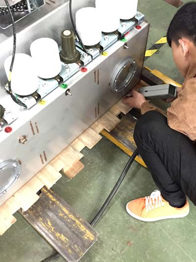
Gas Tank Seal Testing
Mechanism Operating Test
We are now halfway through the gas insulated switchgear technical specification.
Let’s begin the mechanical operation test.
Mechanism Operating Test
The load switch is categorized into five types.
It must be:
- Reliable
- Flexible
- Without blockage and;
- Too much operation force.
The load switch must be switched on dependable not to reset after impact.
You should also keep in mind that the load switch shouldn’t be closed.
Under rated working voltage, the load switch could be categorized into 5 electrical switchgear components.
With this, the action must be reliable and accurate.
At 120% rated operating voltage, the load switch must be able to close at 65% rated operating voltage.
The load switch must be able to open dependably more than three times.
All signal circuits, lights, and instructions must be reliable and accurate.
Protection circuit electrical drive must be right, reliable, and shouldn’t be mistaken.
The setting values of every medium voltage switchgear component must be precise and the error within the prescribed limits.
The operation of the voltage and current indicating circuits must be correct and accurate as well.
The meter must be precise, along with three tests.
The loop action of the electrical interlock in the metering loop must be:
- Reliable
- Accurate
- Interlocking between various cabinets and;
- The analog interlocking test must be performed.
The other two circuit transmission must follow the gis substation design details requirements.
Five Anti-Locking Test
When the load switch is on the closing spot, the ground switch must not be closed.
If the grounding switch is in that position, the load switch shouldn’t be closed.
If the load switch is closed, the isolating switch must be closed first.
The isolating switch after the load switch is switched off must be broken down.
The front door of the gis switchgear can only be opened if the grounding switch is closed.
If the door of the gas insulated substation is opened, the ground switch and load switch aren’t operational.
Micro Water Test
- Sf6 gas insulated switchgear may be exposed to moisture during manufacturing, transportation, installation, and overhaul
- Insulating components of the sf6 gas insulated switchgear with a small amount of water
- Adsorbent of switchgear contains water
- SF6 gas contains water
- The diameter of the water molecules is much smaller than the diameter of the SF6 gas molecules, the micro-sand eyes, the improper installation of the seal ring, and other small gaps, water molecules can enter
After SF6 gas is poured into the gas tank, it should be allowed to stand for several hours, and then the water test should be carried out. When delivered, the micro water should be less than 150PPM.
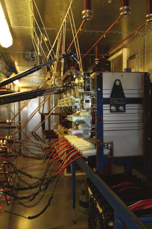
Power Frequency Withstand Voltage Test
The power frequency withstand voltage test is the most effective and direct method for identifying the insulation condition of electrical equipment. It can judge whether electrical equipment can continue to operate, and it is also an important means to avoid insulation failure.
Main Circuit Resistance Test
A circuit resistant tester is utilized to calculate the resistance of the main circuit.
The measured resistance must not be over than 480 micro European every item.
Every measure is three times, and the maximum value is taken.
This excludes the fuse.
Protection Circuit Grounding Continuity Inspection
The DC resistance between any protective conductor and metal structure must not exceed ten milliohms.
The plug bolt, operation handle and two terminal frames of the switch must be measured.
The measured resistance must be less than ten million.
The DC resistance of your door lock, as well as main grounding, must be less than 100 milliohms.
Only single point and ground loop are attached to about one place along with melon-shaped pads.
Two or more connection points must be linked by:
- two gourd pads
- two spraying components connected
- two spraying parts.
These are utilized for claw-shaped pads.
Factory Accessory Checklist Check
The gas insulated switchgear specification and quantity of the fittings on the packing list must be stated explicitly.
Plus, the name of the gis substation system must be specified.
The fittings in the box must follow to the quantities and specifications on the packing list.
After the inspection is qualified, the box is covered with an adhesive paper.
The opening hole of the busbar screen is reserved correctly.
The engineering name, installation location, and direction are marked correctly at the non-lap point.
It must be placed in position correctly.
There you have it.
Hopefully, you’ve understood the right gas insulated switchgear training for gas insulated switchgear technical specification.
Are you still with us?
Don’t miss the next and final chapter of our e-book.
In the next chapter, we will discuss gas insulated switchgear maintenance.
Chapter 6: How to Install Gas Insulated Switchgear: Gas Insulated Switchgear Installation Procedure
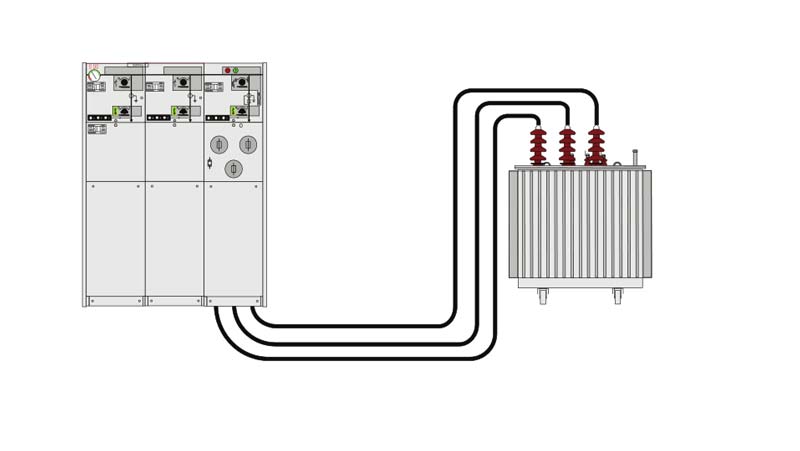
A series of SG6 gas fully insulated and fully sealed metal closed switch equipment (C-GIS) is the new generation of miniaturized gas fully insulated products.
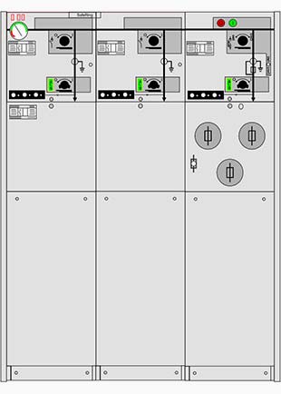
The gas insulated switchgear single line diagram combines the mix of flexible expansion and the fixed unit.
It’s not only appropriate for the distribution of the ring network of the requirements of the user terminal.
It also offers the requirements of the distribution of the ring network of the user terminal.
It meets the needs of several two substations for flexible usage of compact switchgear.
Now, after you understand the different structure and parts of gas insulated switchgear, what’s next?
It’s time for you to know the gas insulated switchgear installation guide.
Without further ado, let’s dig more in-depth about the gas insulated switchgear layout.
Gas Insulated Switchgear Installation Guide
For the gas insulated switchgear layout and installation, you need to prepare the following tools:
For operation equipment, you need:
- Crowbar
- Roller
- Jack roller
- Forklift
- Mobile crane
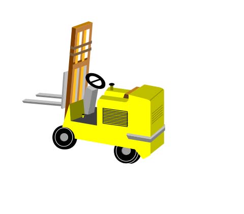
Forklift
Here are the other tools you need for the gas insulated switchgear installation guide:
- Cleaner
- Foot adjustment gasket
- Sleeve wrench
- Combined ratchet wrench
- Torque wrench
- Screwdriver, and so one
The abovementioned tools are selectively organized based on the actual gas insulated switchgear layout.
Are you now ready?
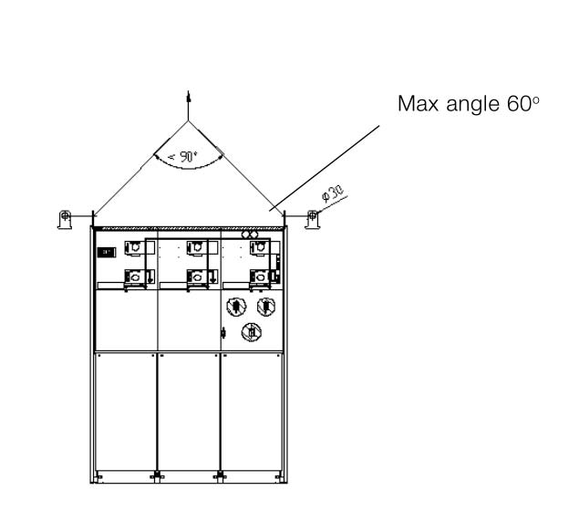
But first, before starting, safety education about hoisting ring cabinet must be paid attention.
You need to check whether the base of the ring cabinet meets the design requirements.
Check also if the installation of channel steel if flat.
Further, confirm if the weather equipment in switchgear is complete and intact.
After you transported the product to the installation site, you need to remember two things.
What is it?
First, make sure to clean the installation location carefully.
That’s because the product must be installed dry and dust-free.
Second, when moving your switchgear equipment, make use of the original transport bracket as further as possible.
What you want here is to prevent the external force on the switch wall throughout your transportation.
What’s more:
Make sure you do not climb to the top of the switchgear.
You can use the forklift or lift to transport the unit to the location near the installation area in the proper installation order.
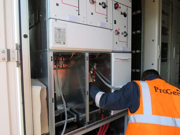
Installation of Body Unit
Install body unit
Have you checked the location order of the gas insulated switchgear single line diagram?
If so, then the switch unit is moved from the transport tray rack to the channel steel based.
After that, it can be moved to the installation location.
Put the first switch unit in the installation area and fix it.
Organize the other delivery units with short distance intervals.
The gas insulated switchgear grounding switch and the load switch should be in the ground position.
The circuit breaker should be operating as well.
Dismantle The Cable Chamber and The Rear Unit Seal Plate
Calibrate the level of the switchgear and the straightness of the position.
If there’s unevenness, the adjustment of the gasket is needed.
Take note:
The bus connection needs extreme basic flatness for the switch.
So, to resolve this:
Fix the switchgear on the base channel steel.
Dismantle the sealing cover of the switchgear unit to be extended.
Align the position of the bus connector.
Connect it correctly according to the expansion approach.
You can use only them to install the unit connected bolt and then resolve the switch unit.
Welding or bolts can fasten the connection between the foundation channel steel and switch cabinet.
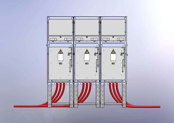
The Connection of Busbars and Cable Accessories
In this gas insulated switchgear layout guide, make sure to check the bus end and cable accessories.
But why?
You need to ensure that there are no scratches whenever installing.
Yes, you read that right.
The light holes on the connection terminals must be aimed at the screw hole on the insulation sleeve.
What’s more:
The two contact surfaces must be kept in great contact without warping and offset.
The double head bolts and the connect screw must be screwed in properly.
Until then, you can check that the cable shield is grounded after the cable is installed.
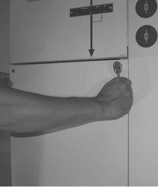
Cable Connection
All the casings should have the same height from the ground.
It must be protected by the cable compartment cover.
To know more information on how to connect the cable, you can check your supply documentation for more details.
Prefabricated cable termination
Cable compartment for C-, D-, and De modules
Bear in mind that it should be installed according to the gas insulated switchgear single line diagram of your manufacturer.
But wait there’s more!
The casing should also be appropriately lubricated.
You can achieve this by using supplied silicone grease.
REMINDER!!
Before you connect the cable, make sure that the ground switch is locked in a closed position.
Alternatively, the sleeve should be covered with a touchable plug before the switchgear unit is positioned into operation.
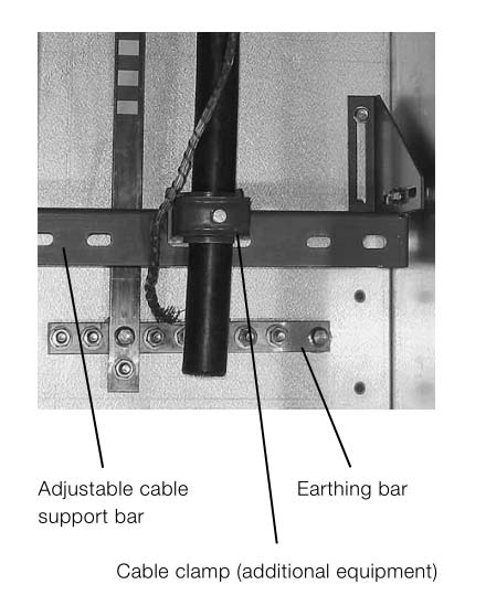
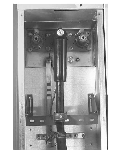
Installation of Straight-Through Current Transformer
Install the current transformer.
The cable shield is reversed through the center hole and is grounded.
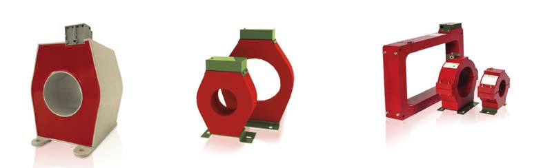
Current transformers
The vacuum circuit breaker module is geared with a protective device.
The cable from the protection device to the existing transformer will be positioned in the cable room.
But why is that?
That’s because it will prepare for connection along with the existing transformer.
BEFORE INSTALLATION
Before starting the installation, you need to check whether the:
- Parameters
- Specifications and;
- Model
of the current transformer follow to the ordered products.
You also need to check whether the installation size of the current transformer is appropriate.
But that’s just part of the story:
Before the cable connection head is assembled, the current transformer should be assembled on its high voltage first.
The 3-phase integrated current transformer should be installed on the cable sleeve before it went out of the factory.
The gas insulated switchgear grounding shield on the cable should be reversed through the center hole of the current transformer.
It must be grounded through the gas insulated switchgear grounding bus in the cable chamber too.
What’s more:
The installation plate of the current transformer must be installed into the cable chamber.
After you install the current transformer, what’s next?
It’s time for the protection device to be connected to the current transformer cable.
You must connect it based on its drawing requirements.
You will find that there are basic requirements for offering overall protection function of the circuit breaker.
And these are:
- The proper connection of the current transformer
- The proper setting of the protection device
Air Pressure
Under the temperature of 20 degrees, the rated pressure of the SF6 gas is 1.4 bar.
Every individual chamber is loaded with SF6 gas density meter along with temperature supplement.
- The density indicator is positioned in the green area.Green is considered as a normal equipment pressure.
- The density indicator is positioned in the red area.Red symbolizes for too low pressure.
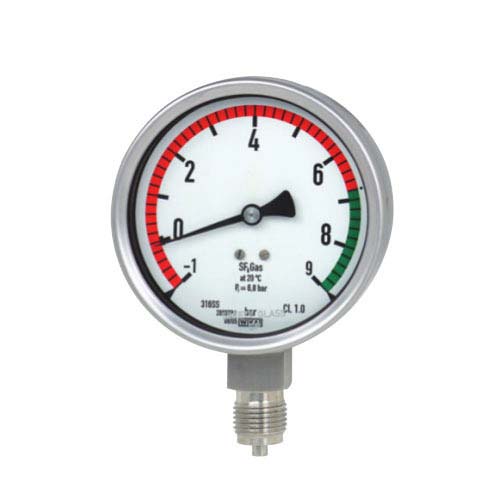
Gas density indicator
This gas insulated switchgear installation guide only describes the operation of gas insulated switchgear. Make sure you follow every gas insulated switchgear single line diagram to achieve a better outcome.
Chapter 7: Gas Insulated Switchgear Maintenance
In this chapter, you will understand everything you need to know about gas insulated switchgear maintenance.
This chapter describes the basic handling and maintenance of gas insulated switchgear components and its standard handling processes.
Without further ado, let’s take a look.
Maintenance of Switchgear Unit
The maintenance work is utilized to keep the electrical switchgear design fault-free operation.
It’s also intended to acquire the most extended service life.
You see:
The gas insulated switchgear preventive maintenance work is composed of the following closely related high voltage switchgear components:
1. Check
It depends on the concrete situation.
2. Maintenance
It measures for keeping the particular working conditions of the equipment.
3. Overhaul
It measures to restore the particular working conditions of the equipment.
Under average circumstances, every component of this product is free of maintenance throughout the life cycle.
Prior installation, you need to check whether the external gas insulated switchgear components are:
- Artificially damaged or;
- Transported
Routine gas insulated switchgear preventive maintenance only requires visual inspection under average operating conditions.
Plus, high-pressure gas insulated switchgear components should be cleaned if needed.
Did you know?
The scheduled service life of a metal enclosed switchgear is 30 years, free of maintenance.
After these years, what will happen?
Why do you need to perform regular electrical switchgear maintenance?
That’s because the high voltage switchgear contains flouring including greenhouse gas SF6.
It will cause climate warming.
The launch and the operation of SF6 switchgear should be gas recovery.
Thus, it should not be released into the atmosphere.
In the usage and treatment of SF6, IEC 62271-3030 High Voltage Switches and Control Equipment – Part 303 “Use and Treatment of Sulphur Hexafluoride” should be observed.
Parts Replacement
Indicator and fuses of gas insulated switchgear components are the common spare parts of this kind of switchgear.
Spare parts can be ordered at your nearest gis switchgear manufacturers at the time of order.
All switches should be operated along with a fitted handle.
Dependable internal mechanical interlocking between the vacuum switch or load switch and the corresponding switch avoids an improper operation.
The operation of the vacuum switch can be further interlocked via padlock.
The earthing switch runs through a quick mechanism to guarantee quick closure.
Product Maintenance
All medium voltage switchgear component in the SF6 gas chamber is free of maintenance throughout its life cycle.
The SF6 gas chamber is soldered by the highest quality of 304 stainless steel.
It guarantees the sealing of the product.
It also safeguards the high voltage switchgear components in the gas chamber from any environmental impacts.
Is the cabinet of your exterior damaged or scratched?
If so, it should be repaired with paint.
But why paint?
Using paint to fix your gas insulated switchgear problems can help it not to corrode.
Further, the operating mechanisms are positioned on the exterior of the air chamber and at the back of the front panel.
That can be easily operated, maintained and changed.
The operating mechanism is treated through surface anti-corrosion.
The moving part is lubricated before leaving the factory.
It allows it to satisfy the service life of your gas insulated switchgear.
However, in some cases, there are worst concerns.
For instance, there’s the bad use of the environment.
If you experience this, you must deal with the needed gas insulated switchgear preventive maintenance of the operating mechanisms.
It includes:
- Proper lubrication and;
- Cleaning up of the dirt
On the other hand, packing products are forbidden from:
- Inversion
- Strong vibration
- A collision during transportation and;
- Loading and unloading.
Products are kept in a dry, moisture-proof and ventilated indoor or warehouse.
Extended storage requires to be treated and lubricated in the transmission part.
Make sure that you checked the environment on a regular basis as well.
With this, the storage life of your gas insulated substation can reach up to 15 years.
When medium voltage switchgear needs to be stored for a limited time, there’s no need for rain protection.
Storage circumstances need to meet the following requirements:
- The ground has enough bearing capacity
- The ground is flat
- Good ventilation, without dust
Fair enough, right?
But wait, there’s more you need to remember.
Part of your gas insulated switchgear inspection is to check the moisture in the packaging.
You need to do it every four weeks.
Try to maintain the reliability of your original product.
The last thing you want is to have a damaged or corroded product.
In the operation of the gis substation design every three to five years, you need to perform small gas insulated switchgear inspection.
You need to:
- check the wear and tear conditions of the parts of the mechanism
- check the condition of the fastener
- eliminate the dust on the surface of the insulation
- add lubricants on the active areas.
Equipment Maintenance
- Check if the grounding of the gas insulated switchgear is good and reliable.
- The SF6 load switch is sealed in a closed device filled with SF6 gas. Check the SF6 barometer to ensure that the air pressure is between 0.4 and 0.5Mpa.
- The pressure gauge will change with the change of external temperature. If the degree exceeds the green range, it should be stopped immediately and notify the company.
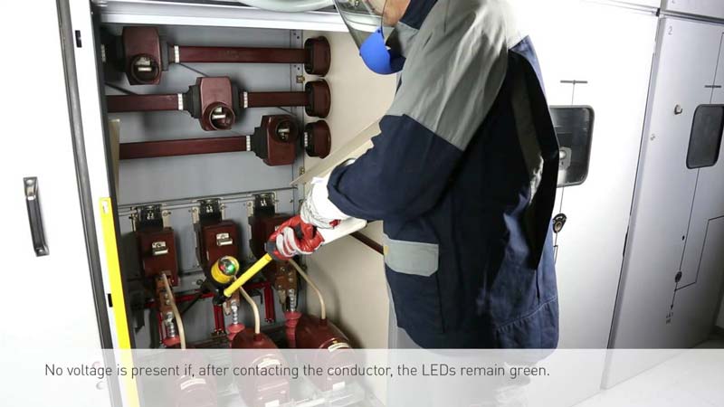
- Check the high-voltage cable, whether the cable head is aging, damaged or discharged, and there is no abnormal sound.
- Check if the live display is normal.
- If there is no abnormality, clean the cabinet casing dust.
- Check if the high-voltage switch operating mechanism is normal.
- If an abnormal situation is found, report it in time, and ask the professional company for repair.
Chapter 8 Gas Insulated Switchgear Troubleshooting: Simple Analysis about the Technical Problem of SF6 Gas Insulated Switchgear
You are now fully aware of the installation and maintenance guide about SF6 switchgear.
So what’s next?
Remember, we are not through yet.
Seriously, how do you fix your switchgear substation in case it suffers from malfunction?
Yes, you read that right.
Think about this for a moment.
Imagine what it would be like if you don’t have the guide on resolving the technical issues of your SF6 substation?
What if you could have the tools you need, right at this point?
There is good news!
In this chapter, we will discuss some troubleshooting tips you need to know.
Let’s get started!
Air insulated substation has become a crucial node of power supply in the urban ring network.
These days, its safe operation directly influences the power supply quality of power enterprises.
What’s more:
In the actual working procedure of sf6 substation, different types of faults will happen.
What will you do when they happen?
That can lead to the reduction of your power supply reliability.
You know that industrial switchgear has a lot of advantages.
These include:
- flexible installation
- small volume
- convenient installation
- high insulation
- full closed and;
- has gradually become a critical power supply node in the city.
However, in the course of its operation, if there’s an issue, it will cause a small or significant impact on your power system.
Now, how can you beat that?
Thus, it’s crucial to assess the problems of quality switchgear.
You need to put forward necessary solutions to guarantee the reliability of power supply.
Common Issues of Commercial Switchgear
The operation state of power switchgear is connected to the power supply quality of power enterprises.
So, you should aim to guarantee the standard operation of sf switchgear.
Unfortunately:
There will be some errors in the gis power system.
Typical failures normally include:
- the connection between the cable and the casing;
- the interception circuit;
- the rejection of circuit breaker
- the insulation failure and more.
Nowadays, the share of ac switchgear in the urban distribution network is higher than of other switchgear.
You see:
Its vital role is self-evident.
It’s reliable and safe operation is connected to the dependable power supply of the user.
Connection Between the Cable and Casing of Power Electric Switchgear
From the failure analysis in the operation of over ten substations, most failures are the issues of the connection between the cable and the casing.
Because of the low height of the cabinet utilized in the single-core cable, it’s not appropriate for the installation of 3-core cable.
It can’t ensure the installation accuracy.
Thus, the height of your cable room must be raised correctly.
Gas Insulated Substation Box Failure
The major fault of the gis electrical substation is that the fully sealed tank causes gas leakage for different reasons.
That leads in the insufficient density of sf6 substation in the fully sealed gas box.
It eventually results in the switch in the standard operation or operation process.
What’s more:
The short circuit happens between the static contact and the switch
Later on, it will cause the accident.
You see:
The leakage position of your gas substation is situated in the cable pile head.
That’s mainly the non-standard in the installation process of the cable.
Also, that results in the pile head to be stressed extremely.
It will cause the crack in the head of your air insulated substation, resulting to the leakage.
Problems of Insulation Fault
Insulation faults have a massive impact on the gis room in the substation.
Simply put:
The causes of insulation problems can be categorized into two types:
- external causes and;
- internal causes.
The internal factor is the quality fault of the switch cabinet.
Many equipment installations don’t follow to the standard.
Why?
That’s because of the limited installation procedure.
That eventually fails the climbing distance to meet the requirements of the installation.
But wait – there’s more!
The ventilation setting of your sf6 substation should be better.
We want here the creepage distance to meet the preferred value.
However, due to several reasons, the ring network often has to be scaled in the concrete implementation procedure.
The air gap isn’t sufficient to meet the demands of the insulation.
Cable Terminal Head Fault
At this level, the common problems of the SF6 gas substation box loop cabinet cause the cable terminal head breakdown.
Do you think what causes it?
It’s due to the production technology or quality issues of the cable terminal head.
That fails your ring network cabinet.
Prevention & Solutions to Common Faults
1. Enhance the Height of the Cable Room
The standard SF6 cabinets cable room is quite small and low.
That’s harder for the installation of the T-type joint of the 3-core cable.
You see:
3-parts of the T-cable are installed in the cable room.
Further, the construction of the site environment is relatively poor.
Thus, the cable connection head isn’t easily installed.
You must raise the height of the sf6 substation cabinet properly.
2. Install Dehumidifier or Take Natural Ventilation
Nowadays, a more efficient method to prevent wet gas from the entering the loop is to block the floor with a sealed fireproof material.
That can avoid wet air and realize the function of stopping small animals.
Indoor ring cabinet can be dehumidified with dehumidification equipment.
Outdoor cable branch box can:
- raise the base height
- seta a specific amount of heat dissipating and;
- breathable holes around the foundation
Simultaneously, the measures must be taken into account for the avoidance of small movable objects.
For instance:
The cable branch box is geared with PT.
The field conditions allow the installation of the dehumidifier.
3. Insulation Protection
Insulation incidents account for a massive amount of the SF6 substation faults.
First of all, you need to pick qualified materials and equipment.
Ensure you have good quality at all times.
Apart from that, the relevant operator should:
- follow the applicable rules and regulations
- improve the technical management standards of overvoltage protection and;
- operate seriously.
To sum up:
Gas insulated switchgear along with its advantages has been widely utilized in several urban power grid systems.
It has somewhat played a crucial role in the protection and control of the distribution system.
Given the mentioned issues, this chapter puts forward the corresponding preventive measures.
We hope you will now achieve the purpose of lessening the failure rate of your operating loop network.
Conclusion
Gas insulated switchgear or gis gas insulated substation have been successfully in use for most than 40 years.
That’s because of its increasing use around the globe.
Higher efficiency and high reliability have been gained over the last decades.
The share of substation switchgear of all projects around the world is massive.
That’s compared to the air insulated substation, and mixed technology substations mirror this situation in figures.
Confidently you now have a better understanding about:
- what is gas insulated switchgear;
- gas insulated switchgear working principle;
- types of gas insulated substations;
- the function of switchgear in substation;
- gas insulated switchgear testing procedure;
- how does gas insulated switchgear work;
- medium voltage switchgear specification;
- gas insulated switchgear operation and;
- gas insulated switchgear preventive maintenance.
Now, do you think you can manage to order your gas insulated switchgear components?
Are you now looking for the best sf6 switchgear manufacturers around the globe?
Don’t look further because Orecco Electric got you covered!
We’ve been in the business of gas insulated switchgear industry for many years.
For any queries or free consultations on the different types of sf6 gas insulated switchgear, feel free to contact our technical team today.