Electrical Distribution Transformer
The electrical distribution transformer is one of the main equipment in power plants and substations. The role of the electrical distribution transformer is not only to step up the voltage to the power supply area but also to step down the voltage to at all levels to meet the needs of electricity.
After the voltage raised by the step-up transformer, the loss of the line can be reduced, the economic efficiency of power transmission can be improved, and the purpose of long-distance power transmission can be achieved. The step-down transformer can change the high voltage to the user’s required voltage at all levels to meet the user’s needs.
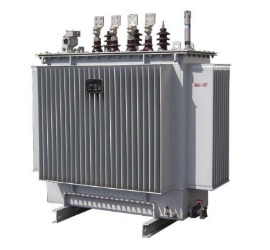
There are two types of electrical distribution transformers according to the classifications of different cooling media: oil filled transformer and dry type cast resin transformer. As one of the leading manufacturers of the electrical distribution transformer, Orecco could provide both of these two types transformers rating power from 30KVA to 10MVA capacity.
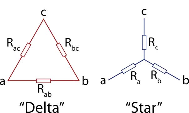
There are two types winding method of the electrical distribution transformers: “D” stands for Delta connection and “Yn” stands for Star connection with neutral line, uppercase letter stands for primary voltage and lowercase letter stands for secondary voltage in the distribution transformers.
There are three main constructional parts of distribution transformer: Primary winding of the transformer, Secondary winding of the transformer and magnetic core of the transformer. The operation of the distribution transformer’s working principle mainly depends on these two circuits linked by a common magnetic flux.
Applications of Electrical Distribution Transformer


Electrical Distribution Transformer: The Ultimate Guide
The electric utility sector was born in 1882.
It’s the time when the very first electric power station, Pearl Street Electric Station in NYC went into work.
You see:
The electric utility sector developed very fast, and transmission, generation stations, and distribution networks have spread around the whole region.
Considering the accessible fuels and energy needs, which are foreseen for the next century, energy is anticipated to be converted increasingly to electricity.
If you are looking for information about distribution transformers, this e-book is perfect for you.
In this guide, we will discuss everything from the definition of distribution transformers, types of distribution transformers, to components parts, maintenance, testing, installation and more.
Happy reading!
Chapter 1: Distribution Transformer Definition: What Is Distribution Transformer?
A distribution transformer is considered an electrical isolation transformer that converts high-voltage electricity to reduce voltage levels acceptable for use in business and homes.
The function of an electrical distribution transformer is straightforward.
That’s to step down the voltage and offer isolation among primary and secondary.
You see:
Electrical energy is passed through the distribution transformers to lessen high-distribution voltage levels down into end-use levels.
About every energy passes through nearly one distribution transformer before being used by a motor, end-use appliance, or other pieces of equipment.
Distribution transformers are seen in every sector of the economy.
Be it:
- industrial
- commercial and;
- residential
Distribution transformers are typically categorized in different ways:
- Applications: power transformer or special transformer
- Number of phases: three-phase or single-phase
- Type of cooling method: dry type or immersed type
- Types of the winding method: double winding transformer, three winding transformer, and autotransformer
General Purpose of Distribution Transformers
Electrical distribution transformers are generally employed for:
- power loads
- motorized machine
- lighting
- supply appliance from electrical distribution systems
They’re either enclosed or ventilated and are accessible with either copper or aluminum windings in average ratings from 50VA to 750kVA.
Given that small distribution transformers don’t produce more heat, a higher amount of such is more likely to be the dry type.
In case you didn’t know yet, dry types aren’t much flammable, and are thus often chosen for use if they should be situated in restricted areas on the premises of the customer.
Electrical distribution transformers are also employed in electric power systems.
The last part of the system at medium voltage is the distribution transformer.
Because of less impedance voltage, this kind of power distribution transformer won’t significantly control the short circuit current when a fault on its secondary part takes place.
It is thus a common practice that the electrical distribution transformers have to be tested to their short-circuit states.
Apart from that, power distribution transformer might be:
- dry type
- oil filled type
Distribution transformers have two major components: oil and core.
The coil is considered a conductor, normally made of low resistance material like copper or aluminum.
Aluminum or copper conductors are wound around a magnetic core to convert current from one voltage to another voltage.
On the other hand, liquid insulation material or the air dry type will surround the conductors and transformer core to insulate and cool the transformer electrically.
A core is designed of magnetically permeable material such as grain-oriented steel.
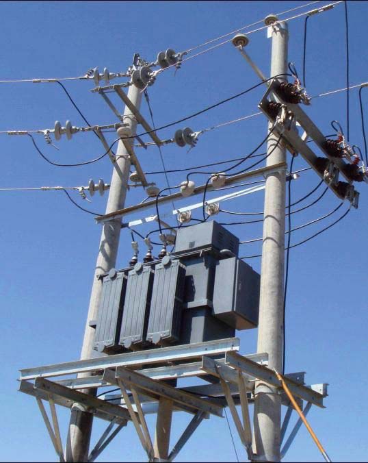
Electrical distribution transformers are either on a concrete pad at ground level or mounted on an overhead pole.
You will discover some evidence to tell that pole mounted 2500 kva transformers disperse heat more simply compared to pad-mounted units.
Thus, it might be more completely loaded.
Distribution Transformer Design
Distribution transformers are designed to grant the efficiency, durability, and reliability needed in commercial, industrial and utility applications.
This transformer is designed for maximum efficiency at 60% to 70% of the complete load.
It’s also designed for a small value of leakage reactance for voltage regulation purpose.
Normally, the secondary winding is designed for start connection while primary winding is designed for delta connections.
They are smaller in size, and typically oil natural circulation cooling method is employed to keep the temperature of the transformer.
Types of Distribution Transformers
As mentioned earlier, there are two different types of electric distribution transformers:
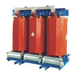
- dry type transformers
- liquid-immersed transformers
Let’s uncover each of them, their features and advantages.
- Dry Type Transformer
Also known as air-cooled transformers, dry type transformers are considered electric transformers.
Why?
Because they do not utilize any liquid (oil) for cooling and heating purposes.
Those also serve as distribution transformers that lessens the high line voltages into low-end user voltages.
You see: air cooled, or dry type transformers achieve this role so effectively and safely.
That’s the major reason why they are typically utilized for indoor applications where several types of transformers are considered too dangerous. Typically, such dry-type transformers have H and F class insulation.
The good thing about dry-type transformer is that:
- They offer high efficiency
- They are very compact in size and appropriate for assignment inside high complex establishments
- They need less service and present dependable service for many years to come
- Oil Immersed Transformers
On the contrary, liquid-immersed transformers are one of kind of electrical distribution transformers that utilize liquid or oil to serve as a coolant.
The word liquid-immersed tells the kind of insulation medium.
Such kinds of transformers are typically outdoors indoors compared to the dry type transformers.
The vast majority of electrical distribution transformers on the utility systems these days are liquid-filled.
That’s because liquid-filled transformer provides the advantages of lower costs, small size, and higher overload abilities rather than with dry types of similar rating.
Some of the advantages of liquid-immersed transformers are:
- They can be utilized at outdoor wherein the dry type transformer can’t be employed due to heating losses.
- Efficient cooling of the transformers.
Application of Distribution Transformer
Did you know that electrical distribution transformers cover a wide array of application?
Applications of distribution transformer
- For Utility – Stable Power Supply for Businesses and Homes
3 phase pole mounted transformer improve grid stability by adapting its transformation ration automatically to correspond to existing load.
They aid utilities accommodate much better infeed from renewable sources while keeping in an allowable voltage band.
Further, they fit in every standard compact station.
- Renewables – Efficient Operation and Low Losses
Mechanically strong, short-circuit proof, and flame retardant, 1500 kva transformer endue even the harshest conditions.
What’s more, they convert the voltage from the generation down to the medium voltage level required for transmission.
- Industrial Applications – Long Service Life and High Efficacy
The winding design of 10kva transformers guarantees dependable absorption of axial, radial, and contraction forces.
They are appropriate for heavy duty drives such as oil rigs, offshore installations, in steel mills, as well as, conveyance facilities.
- Infrastructure – Maximized Energy Efficiency and Lessened Downtime
Similar to infrastructures of big buildings, data centers also depend on electrical distribution transformers to control the energy they source and maintain regular losses less.
Chapter 2: Distribution Transformer Parts
Distribution transformers construction is comparatively less difficult than a substation transformer.
Even though both have the same principle of operation and that is to convert the voltage from a greater level to a smaller voltage level, their basic components differ massively.
Found below are the fundamental and different parts of the power transformer:
Parts of Distribution Transformer and Their Functions
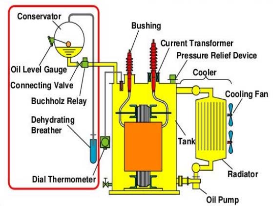
Main Oil Tank
Windings are positioned and saturated in oil
Expansion Oil Tank
This is installed above the main oil tank on the exterior transformer frame.
It’s also linked to the main tank via a metallic tube.
Here, oil can contact freely and extend during loading and therefore the temperature of the oil decreases and increases.
Loading can rise expansion of at least 8%.
The tank compensates any loss in oil which may take place in the main tank.
Bushing
The bushing is accountable for linking the internal windings of the transformer along with the external electrical network.
It isolates the internal windings from the body of the transformer.
Bushings are secured with flanges to prevent any dust, dirt, and humidity from reaching the point of contact.
Radiator
Included to boost the cooling efficiency of the transformer and is geared with a pump that pumps oil continuously in the radiator.
In that case, cooling is expected to be “natural air” as it varies on natural circulation and air cooling the oil.
Often, fans are included to the radiator.
The radiator action is typically known as “forced action” as it uses radiator pump and fans.
Thermal Relay
The thermal relay is employed as an indicator of winding temperature.
It can also be utilized to trigger alarms or fans utilized with big transformers.
Explosion Vent and Pressure Relief Device
These two lessens pressure inside the distribution transformer via external pressure release to prevent an explosion of the transformer.
Contacts and Temperature Detector
If you want to track oil temperature and when the temperature goes beyond a particular limit, the transformer is disconnected from the service.
Oil Indicator
This tells the level of oil in the conservator unit.
Did you know that the decrease in oil could cause flashover when it’s not fixed?
Breather Unit
In case you didn’t know yet, any reduction in oil is being compensated by the conservator tank.
That results to lessen in oil in the conservator tank, and the air is pulled from the outside through what’s called as dehydrated breathing unit.
The unit includes “silica gel” which absorbs any moisture existing in the oil.
Moreover, silica transforms its color from blue to pink when it is not able to absorb moisture.
Buchholz Relay
Positioned when a conservator tank is employed, as it shown errors ad faults like oil loss level goes less, improper oil flow among the transformer and the oil tank.
You see:
It indicates gas emission inside the transformer because of any strange operation.
An example of this is a too much short circuit or loading.
It can issue a control alarm that can be employed to disconnect the transformer.
It’s geared with a release valve in case oil go beyond its level.
The gas color specified the kind of fault in the distribution transformer:
- Black fumes – Burn out and oil decomposition
- Yellow fumes – Insulation fiber burn
- White fumes – Insulation paper failure
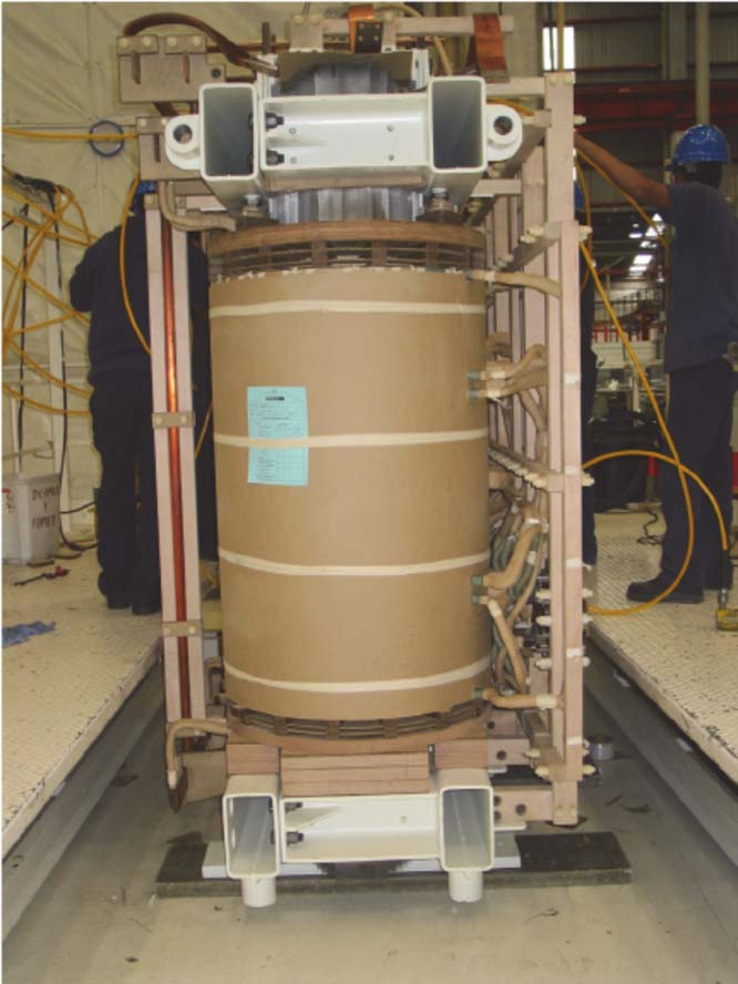
Distribution Transformer Construction
The construction of an electrical distribution transformer includes two active components:
- Ferromagnetic core
- Windings
Throughout the transformer sector, the windings and core together are typically known as the “active part.”
You see:
The passive part of the distribution transformer is the cooling system.
Most distribution transformer tanks are made with cooling fins.
In the case of radiators, the goal of cooling fins is to boost the accessible contact surface for the cooling air.
Nonetheless, in hermetically sealed designs, the cooling fin also allows a level of flexibility that is required to accommodate the contraction and expansion of the liquid because it cools and heats, due to ambient temperature and load.
That enables the tank to be completely loaded, with the obvious benefit of extending the service life expectancy of the transformer and lowering maintenance.
In particular cases, for example, severe dimensional limitations or small ratings, the fans turn out to be small that they are no longer flexible.
That requires the use of a gas cushion to enable the expansion of the liquid.
What’s more:
The gas cushion maintains the internal pressure in the acceptable limits allowed by tank flexibility.
Often, some clients indicate that a conservator should be fitted on top of the distribution transformer tank to serve as an expansion tank for the cooling liquid.
Further, the conservator is frequently fitted along with a gauge glass, an air dryer, and air vent to guarantee that dry air can come into contact along with the cooling liquid, and just at atmospheric pressure.
When the dryer isn’t maintained properly, it can lose its efficiency and permit damp air to come in contact along with the cooling liquid.
Chapter 3: Distribution Transformer Connections
Why Distribution Transformer Secondary Side Is Always Star Connected
Delta star connected transformers are employed in low power distribution along with the primary windings.
It offers a 3-wire balanced load to the utility firm while the secondary windings offer the needed fourth wire neutral or earth connection.
Distribution Transformer Connections
You see:
If the secondary or primary have different kinds of winding connections, delta or star, the overall becomes a ratio of the transformer turns more complicated.
When a 3-phase transformer is linked as star-star (Yy) or delta-delta (Dd), then the transformer could have a 1:1 turns ration.
That’s the output, and input voltages for the windings are equal.
In simple terms, the essential features of having a Star connected secondary is because:
- When secondary neutral is grounded, phase to earth fault will run just the secondary side relaying.
That scheme separates the secondary earth fault from the primary side.
- The star secondary is much steady on unstable loading.
- Third harmonic current will be distributed into the transformer itself and will not be permitted to flow within the supply lines.
- It can supply both 1 phase load and 3 phase load.
Distribution Transformer Design
A basic 2-winding electrical distribution transformer design includes of every winding being wound on an individual soft iron climb or core that offers the needed magnetic circuit.
The magnetic circuit, more typically known as the “transformer core” is made to offer a way for the magnetic field to flow freely.
That is essential for the generation of voltage among the two windings.
Nonetheless, that kind of transformer design where the two windings are coiled on individual limbs isn’t very effective.
That’s because the secondary and primary windings are well detached from one another.
That leads in a low magnetic coupling among the two windings and big amounts of magnetic flux leakage from the distribution transformer.
However, as well as this oval shapes design, there are various kinds of transformer designs accessible which are employed to surpass such inadequacies, generating a small compact transformer.
The effectiveness of a basic distribution transformer design can be enhanced by bringing two windings in close contact with one another.
Thus, it enhances the magnetic coupling.
It concentrates and increases the magnetic circuit around the coil, which may strengthen the magnetic coupling among the two windings.
However, it has the impact of raising the magnetic loses of your transformer core.
In every kind of transformer design, the central iron core is made from an extremely porous material made from skinny silicon steel laminations.
Such thin laminations are collected together to offer the needed magnetic path along with the least of magnetic losses.
Plus, the resistivity of the steel sheet is quite high.
Hence, lowering any current loss by creating the laminations so thin.
Transformer Winding Connection
Transformer windings create another crucial part of a transformer construction.
Transformer winding connection
That’s because they’re the major current-carrying conductors would around the coated sections of the core.
You see: in the single-phase 2 winding transformers, 2 windings would be existing.
The one that is linked to the voltage source and makes the magnetic flux is known as the primary winding.
The second winding, on the other hand, is known secondary wherein a voltage is induced, consequently of mutual induction is achieved.
When the secondary output voltage is fewer than that of the primary input voltage, your electric transformer is now referred to as a “step down transformer.”
When the secondary output voltage is higher, your primary input voltage is now referred to as a “step-up transformer.”
3 Phase Transformer Winding
Did you know that three phase distribution transformer is the support of electrical power distribution whether star or delta connected windings?
Hence far you’ve looked at the operation and construction of the single-phase, two winding voltage transformer that can be employed to decrease or increase its secondary voltage.
That’s with detail to the primary supply voltage.
Nevertheless, voltage transformers can be made for connection to not simple 1 single phase, but for 2 phases, 3-phases and 6-phases and even intricate combinations approximately 24 phases.
You see, 3-phase is employed for electrical power generation, distribution, transmission, and other industrial applications.
3-phase supplies have lots of electrical benefits compared to single phase power.
That’s true if you consider 3-phase distribution transformers, you need to deal with 3 alternating currents and voltages opposing in-phase time by 120 degrees.
Distribution Transformer Are Connected in Configuration
For those distribution transformers which has a single phase primary configuration, cost and size raise with the number of leads.
Single-phase distribution transformers which employ the quad configuration have two windings in the primary side where every winding has a tap which can accept 2 nominal voltages.
Further, devices with five lead voltage selectors can receive 5 potential nominal voltages.
A 3-phase distribution transformer is connected in wye or delta configurations.
You see: electrical distribution transformers which have a ladder configuration includes:
- windings in a cascade
- a collection of inductances connected between end-to-end windings
And as a general rule of thumb, a ladder is the least economical primary configuration.
In case you didn’t know yet, an electrical distribution transformer is connected in a wye-wye transformer or delta y transformer configurations.
A delta-wye transformer features a primary winding connected in a Y and a secondary winding connected in a delta y transformer, and the secondary winding is connected in a Y.
Options for 3-phase distribution transformers is consist of:
- international
- delta-single phase
- wye-single phase
- wye-delta
- wye-wye
- delta-wye
- delta-delta
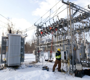
Chapter 4: Installation of Distribution Transformer
The installation of dry type transformers should be free of dust, and the relative humidity should be kept below 70%.
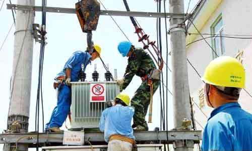
Installation of distribution transformer
Foundation acceptance of felted transformer and box-type substation is qualified.
The transformer inlet and outlet reserved holes and related embedded parts embedded in the electrical conduit and cable conduit embedded in the foundation are inspected to meet the requirements.
The high-voltage electrical equipment of box-type substation, which is composed of three independent units of high-voltage switchgear, low-voltage switchgear, and transformer, has passed the handover test according to the “Standard for Handover Test of Electrical Equipment in Electrical Installation Engineering” (GB50150).
Operator:
Construction workers must undergo formal vocational training and hold certificates.
- Transformer installation should be in the right place with complete accessories, and the oil level of oil immersed transformer is normal without oil leakage.
- The grounding trunk is directly connected with the neutral point of the transformer at the low voltage side. The grounding trunk is directly connected with the N-bus and PE-bus of the box-type substation. The bracket or shell of the transformer box and the dry-type transformer shall be grounded (PE). All connections shall be reliable, fastening and anti-loosening parts shall be complete.
- Transformers must pass the handover test as stipulated in the Standard for Handover Test of Electrical Equipment in Electrical Installation Engineering (GB50150).
- The base of box type transformer and floor type distribution box should be higher than the outdoor floor. The surrounding drainage is unobstructed. Bolts fixed with anchor bolts are complete and tightened firmly. Metal box type transformer secrets and floor type distribution box, the box should be grounded (PE) or zero (PEN) reliable, and marked.
- The handover test of box type substation must comply with the requirements.
Why Neutral of Distribution Transformer Is Earthed
The primary and secondary connection, grounding and control pipelines of transformers should meet the requirements of corresponding technical standards.
The construction of the one or two lead should not directly bear the stress of the transformer bushing.
Transformer zero line and neutral grounding wire should be laid separately. Insulated wires should be used for working lines.
In the grounding circuit of the transformer neutral point, it is suitable to make a removable connection point near the transformer.
The control wires of the oil immersed transformer accessories are insulated conductors with oil resistance.
The wires close to the box wall are protected by metal hoses and arranged neatly.
The junction boxes should be well sealed.
Chapter 5: Distribution Transformer Maintenance and Testing:
Maintenance of Distribution Transformer
Staff members should regularly do a good job of chromatographic inspection of transformer insulation oil.
They must check the indicative value of the hydrogen monitoring device.
That’s to ensure timely detect abnormal conditions that may exist in the transformer.
Maintenance of distribution transformer
When the transformer is in normal operation, the temperature of the main transformer, the high-voltage transformer and the start-up/standby transformer are processed and printed out by computer every hour.
The temperature of the transformer is recorded during a periodic inspection.
According to the regulation of “Equipment Switching Test System On a Regular Basis.”
- the coolers of the main transformer,
- high-speed transformer and
- start/standby transformer
are tested and switched over every half month.
According to the regulation of “Regular Switching Test System of Equipment.”
- the on-load voltage regulating device of the main transformer,
- plant high-voltage transformer and;
- start/standby transformer is tested by remote control of Tap-Changer every half month. To inspect the main transformer:
- high-speed transformer and
- start-up/standby transformer should be assessed according to the regulation of “Equipment Regular Switchover Test System.”
Distribution Transformer Protection
The secondary handling of the felting transformer should be done by the lifting industry.
With the help of electricians, preferably by automobile hoisting or chain hoisting.
It is better to transport the transformer by automobile when the distance is long, and firmly fixed by wire rope when the distance is long, and running smoothly.
This is to reduce vibration as far as possible.
When hoisting a felting transformer, the rigging must be inspected to be qualified.
The wire rope must be hung on the hook of the oil tank and not on the hanging ring of the upper disk.
The hanging ring is only used as the hanging core.
The high and low voltage porcelain bottles should be covered and protected by wooden boxes or cartons when the transformer is transported.
There should be no shock or serious vibration during the transporting process.
When the transformer is used for mechanical traction, the focus should be below the center of gravity of the transformer.
This is to prevent inclination, and the inclination angle of transportation should not exceed 15 degrees to prevent the deformation of the internal structure.
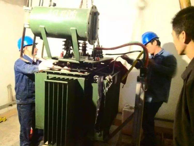
Distribution Transformer Repair
Distribution transformer repair
Abnormal handling of transformer oil level
The following measures should be taken when the transformer oil level is significantly reduced.
- If oil leakage is caused for a long time, additional oil should be added and repaired according to the leakage condition.
- If the oil level is greatly reduced due to the low oil temperature, the operation mode of the cooling device should be appropriately adjusted.
- During the process of refueling, heavy gas protection should be withdrawn from the “switch” to the “signal.”
After refueling, the heavy gas protection trip will be resumed.
Treatment of Transformer Oil Flow Interruption
- Check whether the oil flow indicator is normal.
- Check whether the power supply of the cooling device is interrupted.
Check whether the standby power is automatically put into operation.
Check whether the oil pump is stopped.
If the cooling device fails, the operation mode at that time should be adjusted.
The load should be connected according to the temperature rise if necessary.
However, the allowable capacity under the cooling condition stipulated by the transformer nameplate should not be exceeded.
Treatment of Transformer During Ignition
All power switches and knife switches should be opened, and the cooler should be stopped.
If the transformer oil is on fire on the top cover of the transformer, the accident discharge valve of the transformer should be opened immediately.
The sprinkler fire extinguishing device of the transformer should be started to make the oil cooled and not easy to burn.
If the internal transformer fault causes a fire, no oil can be discharged to prevent the transformer from exploding.
If the transformer shell bursts and ignites, all the oil in the transformer must be placed in the oil storage pit or tank.
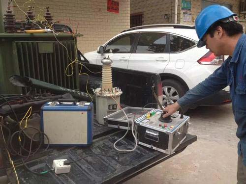
How to Test Distribution Transformer?
Power transformer tests are generally divided into two types:
- Factory test and;
- Handover preventive test.
Here we only introduce preventive handover tests.
The handover preventive test mainly includes:
- handover check,
- overhaul,
- minor repair and
- troubleshooting test.
The preventive test of transformer transfer can be divided into two parts:
- insulation test and
- characteristic test.
Insulation Test
Measure The Insulation Resistance and Absorption Of Winding
The transformer should be put into operation after safety and maintenance.
The insulation resistance between primary and secondary windings and between primary and secondary windings should be measured by Megohmeter after long-term shutdown or during preventive tests every year.
Windings rated at 1000V above 2500V megohmmeter, its measuring range is generally not less than 10000M, 1000V below 1000V with 1000V megohmmeter.
When measuring, the non test winding is grounded.
The insulation resistance and absorption ratio after overhaul and during operation are not generally prescribed.
It should be compared with the data measured before.
If there is a significant decline, the insulation should be analyzed in advance to determine the quality of the insulation.
The insulation resistance should be converted to the same temperature when compared.
Measuring The Leakage Current of the Winding and Bushing
A power transformer with a voltage of 35 kV or more and a capacity of 10 000 kVA or more must measure the leakage current of windings and bushings after overhaul and during preventive tests, and read the leakage current of the high voltage terminal for 1 minute.
Measuring The Tangent Value of the Dielectric Loss Angle of the Winding Together with the Bushing Tan Delta
Transformers with a capacity of 3150 kVA and above shall be tested after installation, overhaul and preventive test.
Non-tested windings shall be grounded (shielded when the M-type tester is used).
Characteristic Test
Measuring DC Resistance of Winding and Bushing
For transformers above 1600kVA, the difference of winding resistance should not be greater than 2% of the three-phase average value.
The difference between lines without neutral point should not be greater than 1% of the three-phase average value.
For transformers of 1600 kVA and below, the phase difference is generally not more than 4% of the three-phase average value.
The line difference is generally not more than 2% of the three-phase average value.
Check The Voltage Ratio of All the Taps of the Windings
This test shall be carried out after transformer installation, overhaul and winding change and internal wiring changes.
After overhaul, the voltage ratio of the corresponding taps should not be significantly different from the nameplate value.
It also should conform to the law.
Transformers with voltages below 35kV and voltage ratios below 3 have allowable deviations of (+) 1% and (+) 0.5% for all other transformers.
Check The Connection of Three-Phase Transformer, and Polarity of Single Phase Transformer Lead Out
After the transformer changes its winding and internal wiring, the internal wiring of the transformer must be consistent with the transformer’s logo (nameplate and symbol on the top cover).
Distribution Transformer No Load Losses
Measurement of no load current and no-load loss of transformer with a capacity of 3150kVA or above at rated voltage.
No-load test should be carried out after the transformer is switched over and the winding is changed.
The measured value should not be changed obviously compared with the test value from the factory.
Efficiency of Distribution Transformer
Up until 1996, the Industry Standards for the Efficiency Distribution Transformers didn’t exist.
Throughout 1996, the “Guide for Determining Efficiency of Distribution Transformers” was published by the National Electrical Manufacturers Association.
It was also called as the distribution transformer efficiency.
The range of the standard is composed of:
- liquid filled distribution transformers
- three phase dry type transformers
- single phase distribution transformers
NEMA TP-1 was rationalized in 2002, and the requirement of TP-1 was added into the Energy Star Program.
Conclusion
Businesses have different options when it comes to purchasing an electrical distribution transformer.
Nevertheless, with so many complicated features of power distribution to consider, looking one which is completely compatible with your equipment and conforms with safety standard observed by operators at the facility isn’t a simple task.
We hope this e-book on distribution transformers have guided you to the right route.
Good luck!